System Product Guide
5-13
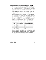
Installing Single In-line Memory Modules (SIMMs)
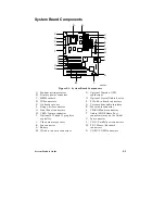
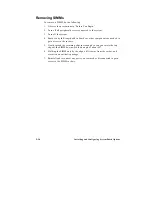
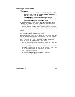
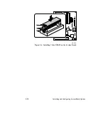
The system board contains four 72-pin, tin lead SIMM sockets. The sockets
are defined as Bank 0 and Bank 1. Two SIMM sockets make up one SIMM
bank. The types of SIMMs that can be installed in the system are as follows:
4 MB, 8 MB, 16 MB, and 32 MB. The computer can support up to 128 MB of
DRAM.
When you install SIMMs, you must completely fill at least one bank. The
computer automatically detects the installed memory, so it doesn’t matter
which bank is used, as long as both sockets in the bank are filled. You can
mix SIMM sizes and types between banks, but not within a bank. For
example, you should not install a 4 MB SIMM in one socket of Bank 0 and
install an 8 MB SIMM in the second socket of the same bank. Likewise, you
should not mix EDO and Fast Page Mode (FPM) SIMMs in the same bank.
You can, however, install 4 MB SIMMs in Bank 0 and 8 MB SIMMs in Bank 1.
You can also install EDO SIMMs in one bank and FPM SIMMs in the second
bank. When adding SIMMs, use only tin lead, 72-pin, EDO or FPM DRAM.
Table 5-4 shows which speed DRAMs should be used with which CPU.
Faster devices can be used but will not improve system performance.
Table 5-4. Required SIMM Speeds
CPU Bus
Speed
Use EDO DRAM of at
Least This Speed
Use Fast Page Mode DRAM
of at Least This Speed
50 MHz
70 ns
70 ns
60 MHz
70 ns
70 ns
66 MHz
60 ns
70 ns
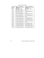
By using various combinations of SIMMs, you can configure the system
memory from 8 MB to 128 MB. Table 5-5 shows the possible combinations of
SIMM types and the resulting amount of system memory. Remember that
each SIMM bank contains two SIMM sockets. Therefore, the amount of
memory in one bank includes the memory installed in both sockets in that
bank.
Summary of Contents for apricot VS660
Page 1: ...SYSTEM PRODUCT GUIDE VS660 apricot MITSUBISHI ELECTRIC ...
Page 2: ...Mini Tower System Product Guide ...
Page 51: ......
Page 55: ...4 4 Taking Your System Apart OM04061 A B A Figure 4 1 Removing the Side cover ...
Page 75: ......
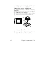
Page 86: ...System Product Guide 5 11 OM03834 Figure 5 3 Removing the CPU Clamp ...
Page 138: ......
Page 139: ......
Page 141: ......
Page 145: ......

