x
Contents
Tables
5-1.
System Board Jumper Block Settings................................................... 5-5
5-2.
ISA Bus Clock Speeds ............................................................................ 5-8
5-3.
Clearances for OverDrive Processor Upgrades.................................. 5-9
5-4.
Required SIMM Speeds ....................................................................... 5-13
5-5.
Memory Options................................................................................... 5-14
D-1.
Supported Resolutions..........................................................................D-4
Figures
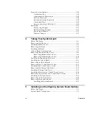
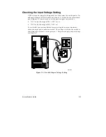
2-1.
Check the Input Voltage Setting........................................................... 2-3
2-2.
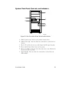
Mini-Tower Front Panel Controls and Indicators .............................. 2-5
2-3.
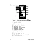
Mini-Tower Back Panel Connectors and Features ............................. 2-6
4-1.
Removing the Side cover....................................................................... 4-4
4-2.
Removing the Bezel................................................................................ 4-6
4-3.
System Slot Numbering Convention ................................................... 4-7
4-4.
Removing a Breakout Expansion Slot Cover ...................................... 4-9
4-5.
Removing an Expansion Slot Cover................................................... 4-10
4-6.
Installing an Add-in Board.................................................................. 4-12
4-7.
Removing the 3.5-inch Drive Carrier ................................................. 4-13
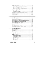
4-8.
Removing the Floppy Disk Drive....................................................... 4-15
4-9.
Installing an Internal Drive ................................................................. 4-17
4-10.
Removing EMI Shields and Filler Panels .......................................... 4-19
4-11.
Installing the Snap-In Slide Rails........................................................ 4-20
4-12.
Installing a 5.25-inch Device ............................................................... 4-21
4-13.
Removing the System Board ............................................................... 4-23
5-1.
System Board Components ................................................................... 5-3
5-2.
System Board Jumper Blocks ................................................................ 5-6
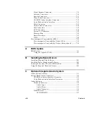
5-3.
Removing the CPU Clamp .................................................................. 5-11
5-4.
Installing a Microprocessor Upgrade ................................................ 5-12
5-5.
Installing SIMMs .................................................................................. 5-15
5-6.
Installing Video DRAM on the System Board .................................. 5-18
5-7.
Replacing the Battery ........................................................................... 5-20
D-1.
Galileo Graphics Control Panel ...........................................................D-2
■
■
■
■
■
■
Summary of Contents for apricot VS660
Page 1: ...SYSTEM PRODUCT GUIDE VS660 apricot MITSUBISHI ELECTRIC ...
Page 2: ...Mini Tower System Product Guide ...
Page 51: ......
Page 55: ...4 4 Taking Your System Apart OM04061 A B A Figure 4 1 Removing the Side cover ...
Page 75: ......
Page 86: ...System Product Guide 5 11 OM03834 Figure 5 3 Removing the CPU Clamp ...
Page 138: ......
Page 139: ......
Page 141: ......
Page 145: ......


