System Product Guide
4-11
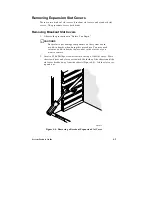
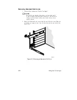
Installing an Expansion Slot Cover
1. Observe the precautions in “Before You Begin.”
2. Using one of the original slot covers, insert the cover into the slot at the
base of the chassis and secure it with a screw.
✏
Note
If you no longer have the original slot cover, use a standard
metal slot cover. The bottom end of the cover fits inside the
chassis, flush with the chassis wall, and the top end secures
to the board guide with a screw.
Installing an Add-in Board
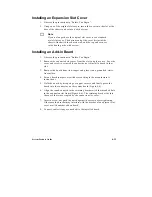
1. Observe the precautions in “Before You Begin.”
2. Remove the expansion slot cover from the slot you plan to use. Save the
cover and screw to reinstall if you decide not to install a board in that
slot.
3. Remove the board from its wrapper and place it on a grounded, static-
free surface.
4. Set any board jumpers or switches according to the manufacturer’s
instructions.
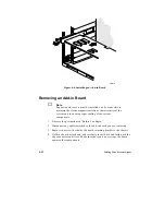
5. Hold the board by its top edge or upper corners and firmly press the
board into the connector
on the system board (Figure 4-6).
6. Align the rounded notch in the retaining bracket with the threaded hole
in the expansion slot frame (Figure 4-6). The retaining bracket fits into
the space that was occupied by the expansion slot cover.
7. Insert a screw, but push the notch against the screw before tightening.
Otherwise the bracket may interfere with the bracket of an adjacent slot
cover or with another add-in board.
8. Connect cables (if any are needed) to the installed board.
Summary of Contents for apricot VS660
Page 1: ...SYSTEM PRODUCT GUIDE VS660 apricot MITSUBISHI ELECTRIC ...
Page 2: ...Mini Tower System Product Guide ...
Page 51: ......
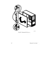
Page 55: ...4 4 Taking Your System Apart OM04061 A B A Figure 4 1 Removing the Side cover ...
Page 75: ......
Page 86: ...System Product Guide 5 11 OM03834 Figure 5 3 Removing the CPU Clamp ...
Page 138: ......
Page 139: ......
Page 141: ......
Page 145: ......

