3.10 AIS FUNCTION
y
yy
3-53
3
3.10
AIS FUNCTION
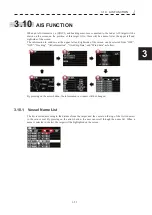
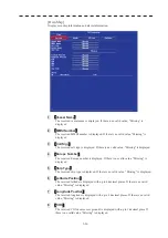
When an AIS transceiver, a (D)GPS, and heading sensor are connected to the radar, AIS target will be
drawn on the screen on the position of this target. Also, there will be a name list at the upper left and
right-side of the screen.
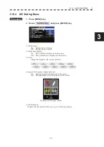
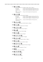
The information in windows at the upper left and right-side of the screen can be selected from “OFF”,
“GPS”, “Docking”, “AIS information”, “Own Ship Data”, and “Wind data” as follow.
By pressing on the arrow button, the information in window will be changed.
3.10.1 Vessel Name List
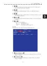
The list is sorted according to the distance from the target, and the vessel on the top of the list is nearest
to the own vessel. By pressing on the arrow button, the user can scroll through the name list. When a
name is selected in the list, the target will be highlighted on the screen.
Summary of Contents for JMR-611
Page 2: ......
Page 24: ......
Page 26: ......
Page 28: ......
Page 33: ...1 5 1 1 4 EXTERIOR DRAWINGS y Fig 1 1 Exterior Drawing of Scanner Unit Type NKE 387 Unit mm...
Page 34: ...1 6 Fig 1 2 Exterior Drawing of Processing Unit Type NDC 1774 Unit mm...
Page 35: ...1 7 1 1 4 EXTERIOR DRAWINGS y Fig 1 3 Exterior Drawing of Operating Unit Type NCE 5923 Unit mm...
Page 38: ......
Page 54: ......
Page 116: ......
Page 118: ......
Page 124: ......
Page 134: ......
Page 136: ......
Page 142: ......
Page 144: ......
Page 154: ......
Page 156: ......
Page 160: ......
Page 164: ......
Page 166: ......
Page 172: ......
Page 174: ......
Page 177: ...APPENDIX Fig 1 Block Diagram of JMR 611...
Page 181: ...APPENDIX Fig 5 Internal Connection Diagram of Control Unit NCM 994...
Page 182: ......
Page 184: ......
Page 186: ......
Page 187: ......


