2-2
2.1
NAMES AND FUNCTIONS OF CONTROL
PANEL SWITCHES
Names and Functions of Control Panel Switches
Simple explanation is described from next page.
Fig 2.2 CONTROL PANEL
1
Ѝ
STBY (Standby) key
2
Ѝ
TX (Transmit) key
3
Ѝ
EBL1/2 (Electric Bearing Line 1/2) key
4
Ѝ
ALARM ACK
(Alarm Acknowledgement) key
5
Ѝ
OFF CENT (Off Center) key
6
Ѝ
GAIN dial
7
Ѝ
P-LINE (Parallel Index
Line) Key
9
Ѝ
RAIN (Rain/Snow Clutter Suppression) dial
10
Ѝ
DAY/NIGHT (Day/ Night Mode) key
11
Ѝ
SEA (Sea Clutter Suppression) dial
12
Ѝ
HL-OFF (Heading Line Off) key
13
Ѝ
TUNE/AUTO (Tune Control/
Automatic) dial
14
Ѝ
ENTER key
16
Ѝ
VRM1/2 (Variable
Range Marker 1/2) key
17
Ѝ
Jog dial
18
Ѝ
Photoshot
ۑ
R
(Screen Capture) key
19
Ѝ
EXP (Echo Expansion)
key
20
Ѝ
SEA STATE key
21
Ѝ
OWN VECT (Own
Ship’s Vector) key
8
Ѝ
BRILL (Operation
LCD Brilliance) key
15
Ѝ
MENU key
22
Ѝ
Track ball
23
Ѝ
+RANGE- (Range
Scale) key
24
Ѝ
RANGE RINGS
(Fixed Range Marker) key
25
Ѝ
PANEL (Operation Panel
Brilliance) key
Summary of Contents for JMR-611
Page 2: ......
Page 24: ......
Page 26: ......
Page 28: ......
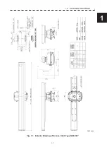
Page 33: ...1 5 1 1 4 EXTERIOR DRAWINGS y Fig 1 1 Exterior Drawing of Scanner Unit Type NKE 387 Unit mm...
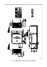
Page 34: ...1 6 Fig 1 2 Exterior Drawing of Processing Unit Type NDC 1774 Unit mm...
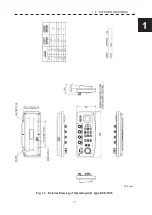
Page 35: ...1 7 1 1 4 EXTERIOR DRAWINGS y Fig 1 3 Exterior Drawing of Operating Unit Type NCE 5923 Unit mm...
Page 38: ......
Page 54: ......
Page 116: ......
Page 118: ......
Page 124: ......
Page 134: ......
Page 136: ......
Page 142: ......
Page 144: ......
Page 154: ......
Page 156: ......
Page 160: ......
Page 164: ......
Page 166: ......
Page 172: ......
Page 174: ......
Page 177: ...APPENDIX Fig 1 Block Diagram of JMR 611...
Page 181: ...APPENDIX Fig 5 Internal Connection Diagram of Control Unit NCM 994...
Page 182: ......
Page 184: ......
Page 186: ......
Page 187: ......


