6-4
(1) Radiator
Check up and clean the radiator.
(2) Rotating
section
(a) Supply Oil Seal
When there is not a grease nipple, the replenishment of grease oil is unnecessary.
Remove the cap on the grease nipple located on the side of the X band radar or on the front of S
band radar at which the radiator is supported, and grease with a grease gun.
Make the oiling every six months. The oil quantity shall be approximately 100 g, which is as much
as the grease comes out of the oil seal. Use the grease of Mobilux 2 of Mobil Oil.
(b) Oiling
gears
Apply grease evenly to the tooth surfaces of the main shaft drive gear and the encoder drive gear
with a spreader or brush. Oiling in short intervals is more effective to prevent the gears from wear
and tear and extend their service life, but oil at least every six months.
Use Mobilux2 of Mobile Oil.
(c) Mounting
legs
Check the mounting legs and mounting bolts of the scanner unit case for corrosion at intervals and
maintain them to prevent danger. Apply paint to them once a half year because painting is the best
measure against corrosion.
z
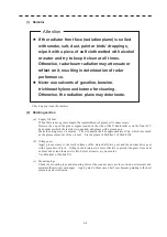
If the radiator front face (radiation plane) is soiled
with smoke, salt, dust, paint or birds’ droppings,
wipe it with a piece of soft cloth wetted with alcohol
or water and try to keep it clean at all times.
Otherwise, radar beam radiation may attenuate or
reflect on it, resulting in deterioration of radar
performance.
z
Never use solvents of gasoline, benzine,
trichloroethylene and ketone for cleaning.
Otherwise, the radiation plane may deteriorate.
Attention
Summary of Contents for JMR-611
Page 2: ......
Page 24: ......
Page 26: ......
Page 28: ......
Page 33: ...1 5 1 1 4 EXTERIOR DRAWINGS y Fig 1 1 Exterior Drawing of Scanner Unit Type NKE 387 Unit mm...
Page 34: ...1 6 Fig 1 2 Exterior Drawing of Processing Unit Type NDC 1774 Unit mm...
Page 35: ...1 7 1 1 4 EXTERIOR DRAWINGS y Fig 1 3 Exterior Drawing of Operating Unit Type NCE 5923 Unit mm...
Page 38: ......
Page 54: ......
Page 116: ......
Page 118: ......
Page 124: ......
Page 134: ......
Page 136: ......
Page 142: ......
Page 144: ......
Page 154: ......
Page 156: ......
Page 160: ......
Page 164: ......
Page 166: ......
Page 172: ......
Page 174: ......
Page 177: ...APPENDIX Fig 1 Block Diagram of JMR 611...
Page 181: ...APPENDIX Fig 5 Internal Connection Diagram of Control Unit NCM 994...
Page 182: ......
Page 184: ......
Page 186: ......
Page 187: ......

