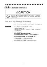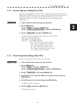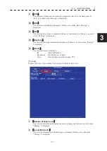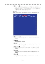
3.6 DISPLAY USER MAP
y
yy
3-43
3
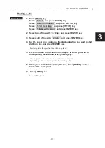
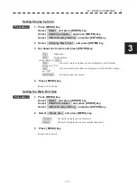
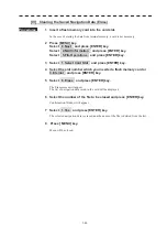
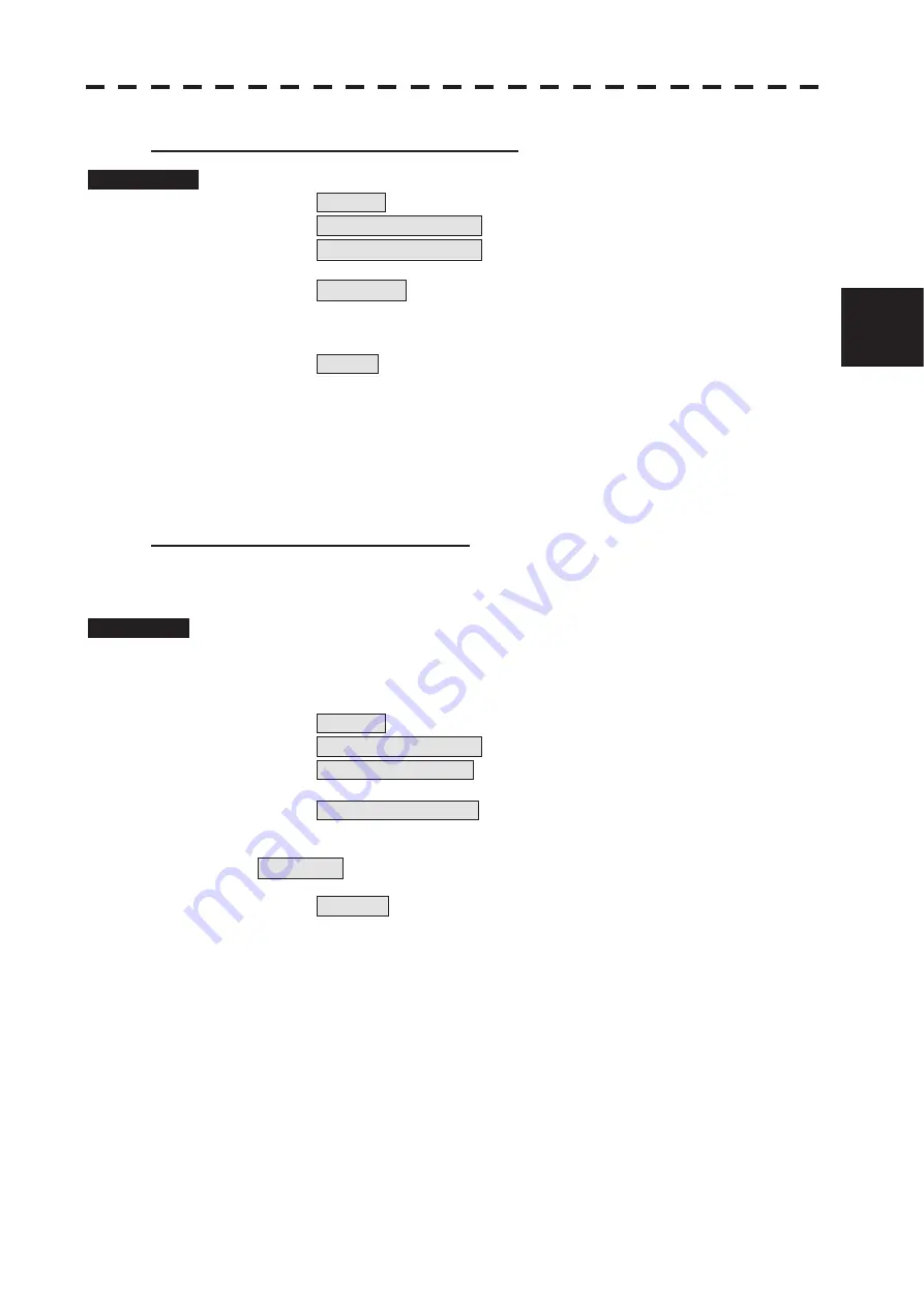
[II] Discarding Navigation Data (Unload).
Procedures
1
Press
[MENU]
key.
Select 8.Next and press [ENTER] key.
Select 4.NAV Information
and press [ENTER] key.
Select 5.File Operations
and press [ENTER] key.
2 Select 4.Unload and press [ENTER] key.
Confirmation Window will appear.
3 Select 1.Yes and press [ENTER] key.
The saved navigation data will be discarded.
4 Press [ MENU] key.
Menu will be closed.
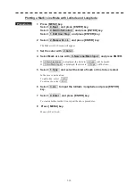
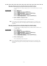
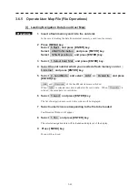
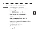
[III] Saving Navigation Data (Save).
Navigation data can be saved when navigation equipment is connected, or the own ship
position on the user map is entered in the manual mode.
Procedures
1 Insert a flash memory card into the card slot.
In the case of saving data to internal memory, a card is not necessary.
2 Press [MENU] key.
Select 8.Next and press [ENTER] key.
Select 4.NAV Information and press [ENTER] key.
Select 5.File Operations and press [ENTER] key.
3 Select 1.Select Card Slot and press [ENTER] key.
4 Select the slot number which you inserted a flash memory card or
3.Internal and press [ENTER] key.
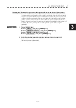
5 Select 5.Save and press [ENTER] key.
The Input File Name menu will appear.
6 Enter the file name to be saved.
Up to 10 characters can be entered.
After the data has been entered, Confirmation Window will appear.
7 Press [ MENU] key.
Menu will be closed.
Summary of Contents for JMR-611
Page 2: ......
Page 24: ......
Page 26: ......
Page 28: ......
Page 33: ...1 5 1 1 4 EXTERIOR DRAWINGS y Fig 1 1 Exterior Drawing of Scanner Unit Type NKE 387 Unit mm...
Page 34: ...1 6 Fig 1 2 Exterior Drawing of Processing Unit Type NDC 1774 Unit mm...
Page 35: ...1 7 1 1 4 EXTERIOR DRAWINGS y Fig 1 3 Exterior Drawing of Operating Unit Type NCE 5923 Unit mm...
Page 38: ......
Page 54: ......
Page 116: ......
Page 118: ......
Page 124: ......
Page 134: ......
Page 136: ......
Page 142: ......
Page 144: ......
Page 154: ......
Page 156: ......
Page 160: ......
Page 164: ......
Page 166: ......
Page 172: ......
Page 174: ......
Page 177: ...APPENDIX Fig 1 Block Diagram of JMR 611...
Page 181: ...APPENDIX Fig 5 Internal Connection Diagram of Control Unit NCM 994...
Page 182: ......
Page 184: ......
Page 186: ......
Page 187: ......

