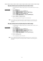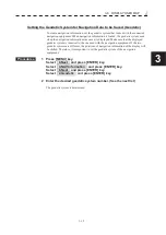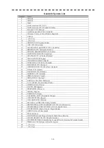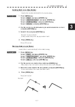
3.5 GENERAL OPERATIONS
y
yy
3-25
3
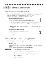
- In the case that NMEA sentence includes GGA but without ZDA/ RMC -
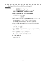
The setting of “Time Zone Setting” and “Local Date” is necessary. After setting, “Time” is displayed
correctly.
- In the case that GPS is not connected to this RADAR -
The settings of "Time Zone", "Local Date", and "Local time" are necessary.
After setting, "Time" is displayed correctly by calculation with inner counter.
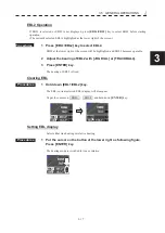
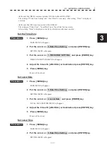
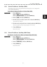
Set the Time Zone
Procedures
1 Press [ MENU] key.
MAIN MENU will appear.
2 Put the cursor on 5.Date/Time Setting and press [ENTER] key.
SETTING MENU will appear.
3 Put the cursor on 1.TIME ZONE SETTING and press [ENTER] key.
TIME ZONE SETTING MENU will appear.
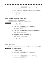
4 Adjust the time with [JOG DIAL] or trackball and press [ENTER] key.
5 Press [ MENU] key.
Menu will be closed.
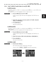
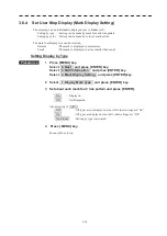
Set Local Date
Procedures
1 Press [ MENU] key.
MAIN MENU will appear.
2 Put the cursor on 5.Date/Time Setting and press [ENTER] key.
SETTING MENU will appear.
3 Put the cursor on 2.Local Date and press [ENTER] key.
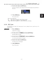
LOCAL DATE SETTING MENU will appear.
4 Adjust the time with [JOG DIAL] or trackball and press [ENTER] key.
5 Press [ MENU] key.
Menu will be closed.
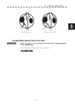
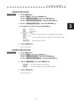
Set Local Time
Procedures
1 Press [ MENU] key.
MAIN MENU will appear.
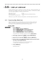
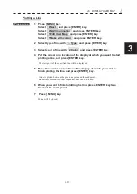
2 Put the cursor on 5.Date/Time Setting and press [ENTER] key.
SETTING MENU will appear.
Summary of Contents for JMR-611
Page 2: ......
Page 24: ......
Page 26: ......
Page 28: ......
Page 33: ...1 5 1 1 4 EXTERIOR DRAWINGS y Fig 1 1 Exterior Drawing of Scanner Unit Type NKE 387 Unit mm...
Page 34: ...1 6 Fig 1 2 Exterior Drawing of Processing Unit Type NDC 1774 Unit mm...
Page 35: ...1 7 1 1 4 EXTERIOR DRAWINGS y Fig 1 3 Exterior Drawing of Operating Unit Type NCE 5923 Unit mm...
Page 38: ......
Page 54: ......
Page 116: ......
Page 118: ......
Page 124: ......
Page 134: ......
Page 136: ......
Page 142: ......
Page 144: ......
Page 154: ......
Page 156: ......
Page 160: ......
Page 164: ......
Page 166: ......
Page 172: ......
Page 174: ......
Page 177: ...APPENDIX Fig 1 Block Diagram of JMR 611...
Page 181: ...APPENDIX Fig 5 Internal Connection Diagram of Control Unit NCM 994...
Page 182: ......
Page 184: ......
Page 186: ......
Page 187: ......


