1-3
1
1.3 CONFIGURATION
y
1.3
CONFIGURATION
Scanner and Transmitted Output Power
SCANNER TYPE
TRANSMITTED
OUTPUT POWER
BAND
JMR-611
7 FT SLOT ANTENNA
4.9 kW
X
Radar Configuration and Ship’s Mains
RADAR
MODEL
SCANNER
UNIT
CONTROL UNIT
SHIP’S MAINS
JMR-611 NKE-387
NCM-994
24
VDC
Notes:
1. An optional rectifier is necessary for using Ship's Mains 100/110/115/200/220/230 VAC.
2. The control unit NCM-994 has a separate structure consisting of the following:
Radar process unit
NDC-1774
Operation unit
NCE-5923
Summary of Contents for JMR-611
Page 2: ......
Page 24: ......
Page 26: ......
Page 28: ......
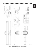
Page 33: ...1 5 1 1 4 EXTERIOR DRAWINGS y Fig 1 1 Exterior Drawing of Scanner Unit Type NKE 387 Unit mm...
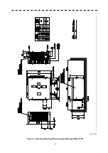
Page 34: ...1 6 Fig 1 2 Exterior Drawing of Processing Unit Type NDC 1774 Unit mm...
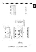
Page 35: ...1 7 1 1 4 EXTERIOR DRAWINGS y Fig 1 3 Exterior Drawing of Operating Unit Type NCE 5923 Unit mm...
Page 38: ......
Page 54: ......
Page 116: ......
Page 118: ......
Page 124: ......
Page 134: ......
Page 136: ......
Page 142: ......
Page 144: ......
Page 154: ......
Page 156: ......
Page 160: ......
Page 164: ......
Page 166: ......
Page 172: ......
Page 174: ......
Page 177: ...APPENDIX Fig 1 Block Diagram of JMR 611...
Page 181: ...APPENDIX Fig 5 Internal Connection Diagram of Control Unit NCM 994...
Page 182: ......
Page 184: ......
Page 186: ......
Page 187: ......

