iii
ە
PRECAUTIONS
ە
ە
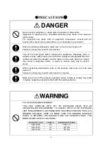
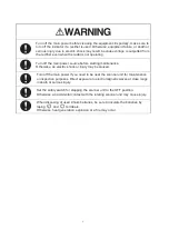
DANGER
Never conduct inspection or repair work of equipment components.
Inspection or repair work by uncertified personnel may result in fire hazard or
electrocution.
For inspection and repair work of equipment components, consult with our
branch office, branch shop, sales office, or our distributor in your district.
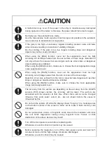
When conducting maintenance, make sure to turn the main power off.
Failure to comply may result in electrocution.
Turn off the main power before cleaning the equipment. Especially when a
rectifier is used, make sure to turn it off since voltage is still outputted from the
rectifier even after the indicator and the radar are turned off. Failure to comply
may result in equipment failure, or death or serious injury due to electric
shock.
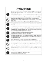
When conducting maintenance work on the antenna,
make sure to turn its main
power off.
Failure to comply may result in electrocution or injuries.
Make sure to turn off the antenna operation switch. Failure to comply may result
in injuries caused by physical contact with the rotating antenna.
FCC RF EXPOSURE STATEMENT
THIS UNIT COMPLIES WITH FCC RF EXPOSURE LIMITS FOR AN
UNCONTROLLED ENVIRONMENT. TO COMPLY WITH FCC RF EXPOSURE
LIMIT REQUIREMENTS, ANTENNAS MUST BE OPERATED MORE THAN AT A
MINIMUM DISTANCE. KEEP TO MORE THAN THE MINIMUM DISTANCE
WHICH IS BETWEEN THE RADIATOR AND ANY PERSON’S BODY. THE
MIMIMUM DISTANCE IS FOLLOWING.
RADIATOR TYPE
LENGTH
MIMIMUM DISTANCE
NAX-16R-6 6ft
308.4
cm
NAX-16R-7 7ft
322.9cm
NAX-16R-9 9ft
379.4cm
Summary of Contents for JMR-611
Page 2: ......
Page 24: ......
Page 26: ......
Page 28: ......
Page 33: ...1 5 1 1 4 EXTERIOR DRAWINGS y Fig 1 1 Exterior Drawing of Scanner Unit Type NKE 387 Unit mm...
Page 34: ...1 6 Fig 1 2 Exterior Drawing of Processing Unit Type NDC 1774 Unit mm...
Page 35: ...1 7 1 1 4 EXTERIOR DRAWINGS y Fig 1 3 Exterior Drawing of Operating Unit Type NCE 5923 Unit mm...
Page 38: ......
Page 54: ......
Page 116: ......
Page 118: ......
Page 124: ......
Page 134: ......
Page 136: ......
Page 142: ......
Page 144: ......
Page 154: ......
Page 156: ......
Page 160: ......
Page 164: ......
Page 166: ......
Page 172: ......
Page 174: ......
Page 177: ...APPENDIX Fig 1 Block Diagram of JMR 611...
Page 181: ...APPENDIX Fig 5 Internal Connection Diagram of Control Unit NCM 994...
Page 182: ......
Page 184: ......
Page 186: ......
Page 187: ......


