5.4 FALSE ECHOES
yy
yyy
5-7
5
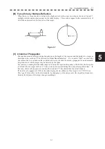
[IV] False Echo by Multiple Reflection
When there is a large structure or ship with a high vertical surface near own ship as shown in Figure5.7,
multiple refection returns may appear on the radar display. These echoes appear in the same intervals, of
which the nearest echo is the true echo of the target.
Figure 5.7
[V] Abnormal
Propagation
The maximum radar detection range depends upon the height of the scanner and the height of a target as
described in the section of “The Horizon for Radar Beam Radiation”. If a so-called “duct” occurs on the
sea surface due to a certain weather condition, however, the radar beam may propagate for an abnormally
long distance, at which a target may be detected by the radar.
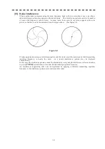
For instance, assuming that the radar range is 4 km (on the repetition frequency of 4000 Hz), the first pulse
is reflected from a target at about 37.5 km or more and received during the next pulse repetition time. In
this case, a false echo appears at a position that is about 37.5 km shorter than the actual distance.
If the false echo appears at 5 NM on the radar display, the true distance of the target is 2+37.5=39.5 km.
This type of false echo can be discriminated by changing over the range scale (the repetition frequency),
because the distance of the target changes accordingly.
Summary of Contents for JMR-611
Page 2: ......
Page 24: ......
Page 26: ......
Page 28: ......
Page 33: ...1 5 1 1 4 EXTERIOR DRAWINGS y Fig 1 1 Exterior Drawing of Scanner Unit Type NKE 387 Unit mm...
Page 34: ...1 6 Fig 1 2 Exterior Drawing of Processing Unit Type NDC 1774 Unit mm...
Page 35: ...1 7 1 1 4 EXTERIOR DRAWINGS y Fig 1 3 Exterior Drawing of Operating Unit Type NCE 5923 Unit mm...
Page 38: ......
Page 54: ......
Page 116: ......
Page 118: ......
Page 124: ......
Page 134: ......
Page 136: ......
Page 142: ......
Page 144: ......
Page 154: ......
Page 156: ......
Page 160: ......
Page 164: ......
Page 166: ......
Page 172: ......
Page 174: ......
Page 177: ...APPENDIX Fig 1 Block Diagram of JMR 611...
Page 181: ...APPENDIX Fig 5 Internal Connection Diagram of Control Unit NCM 994...
Page 182: ......
Page 184: ......
Page 186: ......
Page 187: ......

