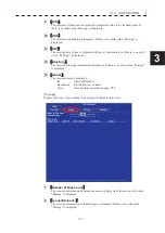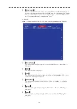
3.7 SCREEN CAPTURE
y
yy
3-47
3
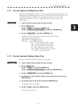
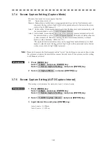
3.7.2 Screen Capture Setting (Save File)
Only when “4.Capture Mode” setting is “Auto-2”, capture data is saved in internal memory.
But these data are deleted when the system is turned off. Therefore, the data must be moved
from internal memory to a flash memory card before turning off in “Auto-2” mode.
(In the case of “Manual” or “Auto-1”, capture data is saved to a flash memory card
automatically.)
Procedures
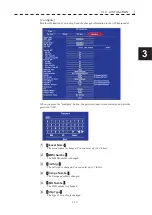
1 Insert a flash memory card into the card slot.
2 Press [MENU] key.
Select 8.Next and press [ENTER] key.
Select 1.Screen Capture Setting and press [ENTER] key.
3 Select 2.Save File and press [ENTER] key.
The folder is created automatically, and the data is saved in the folder.
Folder is created in each one hour.
Folder name : YYYYMMDD_hhmm
Data name : YYYYMMDD_hhmmss
YYYY : “year” when folder or data is created.
MM : “month” when folder or data created.
DD : “day” when folder or data is created.
hh : “hour” when folder or data is created.
mm : “minute” when folder or data is created.
ss : “second” when data is created.
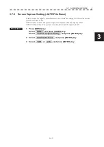
3.7.3 Screen Capture Setting (Erase File)
Erasing of a capture data in a flash memory card is possible.
Procedures
1 Insert a flash memory card into the card slot.
2 Press [MENU] key.
Select 8.Next and press [ENTER] key.
Select 1.Screen Capture Setting and press [ENTER] key.
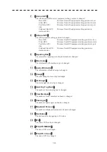
3 Select 3.Erase File and press [ENTER] key.
4 Select folder name in which data to be erased is saved and press
[ENTER] key.
5 Select file name to be erased and press [ENTER] key.
Confirmation Window will appear.
6 Select 1.Yes and press [ENTER] key.
The capture data is erased.
Summary of Contents for JMR-611
Page 2: ......
Page 24: ......
Page 26: ......
Page 28: ......
Page 33: ...1 5 1 1 4 EXTERIOR DRAWINGS y Fig 1 1 Exterior Drawing of Scanner Unit Type NKE 387 Unit mm...
Page 34: ...1 6 Fig 1 2 Exterior Drawing of Processing Unit Type NDC 1774 Unit mm...
Page 35: ...1 7 1 1 4 EXTERIOR DRAWINGS y Fig 1 3 Exterior Drawing of Operating Unit Type NCE 5923 Unit mm...
Page 38: ......
Page 54: ......
Page 116: ......
Page 118: ......
Page 124: ......
Page 134: ......
Page 136: ......
Page 142: ......
Page 144: ......
Page 154: ......
Page 156: ......
Page 160: ......
Page 164: ......
Page 166: ......
Page 172: ......
Page 174: ......
Page 177: ...APPENDIX Fig 1 Block Diagram of JMR 611...
Page 181: ...APPENDIX Fig 5 Internal Connection Diagram of Control Unit NCM 994...
Page 182: ......
Page 184: ......
Page 186: ......
Page 187: ......

