2-3
2.1 NAMES AND FUNCTIONS OF CONTROL PANEL SWITCHES
yy
2
ձ
[STBY](standby) key
Use this key to turn on the power of the equipment.
Use this key also to switch the equipment from a transmitting state to standby state.
The power can be turned off by pressing the
[STBY]
key and
[TX]
key concurrently while the
power is On.
ղ
[TX](Transmission)
key
At expiration of the pre-heat time after the power is turned on, Preheat of the transmit / standby
indicator (Upper left of the display on page 2-1) changes to Standby .
If this key is pressed subsequently, transmission starts.
ճ
[EBL1/EBL2] (Electric Bearing Line 1/2) key
Use this key to display and select EBL1/2. If the key is pressed for several seconds, the EBL will
disappear.
մ
[ALARM ACK] (Alarm Acknowledgement) key
Use this key to acknowledge a failure alarm.
To stop the alarm, press this key while the alarm sound is emitted.
If multiple alarms occur, press this key same time as the alarms.
յ
[OFF CENT] (Off Center) key
Use this key to shift the own ship’s position.
ն
[GAIN] (Gain) dial
Turn the dial to adjust the reception gain of the radar.
Turn the dial clockwise to increase the gain.
շ
[P-LINE] (Parallel Index Line) key
Use this key to display and select P-line 1/2. If the key is pressed for several seconds, the P-line will
disappear.
ո
[BRILL] (LCD Brilliance) key
Use this key to adjust the brilliance of Alpha-screen (LCD monitor).
չ
[RAIN] (RAIN/SNOW Clutter Suppression) dial
Turn the dial to suppress images by rain / snow clutter.
Turn the dial clockwise to increase the effect of suppression.
պ
[DAY/NIGHT] (DAY/NIGHT MODE) key
Use this key to switch the color and brightness of the screen that have been set in advance.
ջ
[SEA] (Sea clutter Suppression) dial
Turn the dial to suppress images by sea clutter.
Turn the dial clockwise to increase the effect of suppression.
ռ
[HL OFF] (Heading Line Off) key
Use this key to clear the Ship’s heading line while this key is pressed.
ս
[TUNE/AUTO] (Tune Control/Automatic) dial
Turn the dial to take tune.
Press the dial for several seconds to switch the mode to manual/ automatic.
Summary of Contents for JMR-611
Page 2: ......
Page 24: ......
Page 26: ......
Page 28: ......
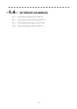
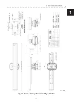
Page 33: ...1 5 1 1 4 EXTERIOR DRAWINGS y Fig 1 1 Exterior Drawing of Scanner Unit Type NKE 387 Unit mm...
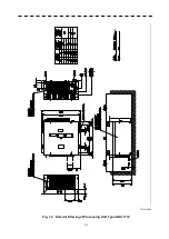
Page 34: ...1 6 Fig 1 2 Exterior Drawing of Processing Unit Type NDC 1774 Unit mm...
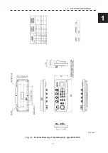
Page 35: ...1 7 1 1 4 EXTERIOR DRAWINGS y Fig 1 3 Exterior Drawing of Operating Unit Type NCE 5923 Unit mm...
Page 38: ......
Page 54: ......
Page 116: ......
Page 118: ......
Page 124: ......
Page 134: ......
Page 136: ......
Page 142: ......
Page 144: ......
Page 154: ......
Page 156: ......
Page 160: ......
Page 164: ......
Page 166: ......
Page 172: ......
Page 174: ......
Page 177: ...APPENDIX Fig 1 Block Diagram of JMR 611...
Page 181: ...APPENDIX Fig 5 Internal Connection Diagram of Control Unit NCM 994...
Page 182: ......
Page 184: ......
Page 186: ......
Page 187: ......

