3.5 GENERAL OPERATIONS
y
yy
3-23
3
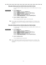
3.5.8 Own Mark
Editing Own Mark Dimension
Procedures
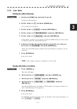
1 Hold press [ MENU] key more than 5 second.
Code menu will be displayed.
2 Put the cursor on 0 and press [ENTER] key.
Service menu will be displayed.
3 Put the cursor on 8. Next and press [ENTER] key.
4 Put the cursor on 1.Ship Dimension and press [ENTER] key.
5 Put the cursor on 1.Own ship and press [ENTER] key.
Set the “Beam”/”Length” of own ship, the position of RADAR antenna, and the position
of GPS1/2’s sensor if you installed two sensors.
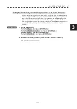
6 If there is 2nd ship (for example barge) connected to own ship, put
the cursor on 2. 2nd ship and press [ENTER] key.
Set the items. If RADAR antenna or GPS sensor is not installed on 2nd ship, set only the
dimension.
7 Press [ MENU] key.
Menu will be closed.
NOTE:
Correct setting is necessary to display the vector correctly.
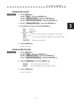
Display Own Mark or 2nd Ship
Procedures
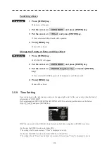
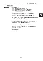
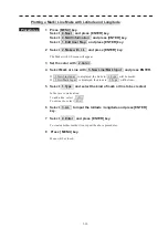
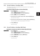
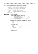
1 Press [ MENU] key .
Main menu will appear.
2 Put the cursor on 6.OWN MARK and press [ENTER] key.
3 Put the cursor on 3.Profile and press [ENTER] key.
4 Put the cursor on 1.Own Ship or 2.2nd Ship and press
[ENTER] key.
Select the shape (Rectangle or Pentagon) or OFF. Rectangle or Pentagon is selected, own
mark or 2nd ship’s mark will be appeared.
5 Press [ MENU] key.
Menu will be closed.
This RADAR can display ten marks or less. For addition of more ships mark display, set
from 3. 3rd Ship to 10th Ship .
Summary of Contents for JMR-611
Page 2: ......
Page 24: ......
Page 26: ......
Page 28: ......
Page 33: ...1 5 1 1 4 EXTERIOR DRAWINGS y Fig 1 1 Exterior Drawing of Scanner Unit Type NKE 387 Unit mm...
Page 34: ...1 6 Fig 1 2 Exterior Drawing of Processing Unit Type NDC 1774 Unit mm...
Page 35: ...1 7 1 1 4 EXTERIOR DRAWINGS y Fig 1 3 Exterior Drawing of Operating Unit Type NCE 5923 Unit mm...
Page 38: ......
Page 54: ......
Page 116: ......
Page 118: ......
Page 124: ......
Page 134: ......
Page 136: ......
Page 142: ......
Page 144: ......
Page 154: ......
Page 156: ......
Page 160: ......
Page 164: ......
Page 166: ......
Page 172: ......
Page 174: ......
Page 177: ...APPENDIX Fig 1 Block Diagram of JMR 611...
Page 181: ...APPENDIX Fig 5 Internal Connection Diagram of Control Unit NCM 994...
Page 182: ......
Page 184: ......
Page 186: ......
Page 187: ......


