xv
11.
㻌
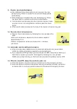
Electric shock (defibrillation)
a) If the AED determines that electric shock is needed, the voice
prompt saying, "Shock is needed" is issued and charging starts
automatically.
b) When charging is completed, the voice prompt saying, "Press
the shock button" is issued and the shock button flashes.
c) The first-aider must get away from the injured or ill person, make
sure that no one is touching him/her, and then press the shock
button.
d) When electric shock is delivered, the body of the injured or ill person may jerk.
12.
㻌
Resume chest compressions
a) Resume chest compressions by following the voice prompts of the
AED.
ʀ
With each compression, depress the chest wall to a depth of
approximately 5 cm.
ʀ
Perform compressions at the rate of about 100 - 120 times
per minute.
13.
㻌
Automatic electrocardiogram analysis
a) When 2 minutes have elapsed since you resumed cardiopulmonary resuscitation
(CPR), the AED automatically analyzes the electrocardiogram.
b) If you suspended CPR by following voice prompts and AED voice prompt informs you
that shock is needed, give electric shock again by following the voice prompts.
If AED voice prompt informs you that no shock is needed, immediately resume CPR.
14.
㻌
When to stop CPR (Keep the electrode pads on.)
a) When the injured or ill person has been handed over to the emergency services
b) When the injured or ill person has started moaning or breathing normally, lay him/her
on his/her side in a recovery position and wait for the arrival of emergency services.
Summary of Contents for JMR-611
Page 2: ......
Page 24: ......
Page 26: ......
Page 28: ......
Page 33: ...1 5 1 1 4 EXTERIOR DRAWINGS y Fig 1 1 Exterior Drawing of Scanner Unit Type NKE 387 Unit mm...
Page 34: ...1 6 Fig 1 2 Exterior Drawing of Processing Unit Type NDC 1774 Unit mm...
Page 35: ...1 7 1 1 4 EXTERIOR DRAWINGS y Fig 1 3 Exterior Drawing of Operating Unit Type NCE 5923 Unit mm...
Page 38: ......
Page 54: ......
Page 116: ......
Page 118: ......
Page 124: ......
Page 134: ......
Page 136: ......
Page 142: ......
Page 144: ......
Page 154: ......
Page 156: ......
Page 160: ......
Page 164: ......
Page 166: ......
Page 172: ......
Page 174: ......
Page 177: ...APPENDIX Fig 1 Block Diagram of JMR 611...
Page 181: ...APPENDIX Fig 5 Internal Connection Diagram of Control Unit NCM 994...
Page 182: ......
Page 184: ......
Page 186: ......
Page 187: ......

