7-6
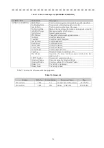
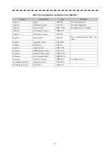
Table 7-6 Circuit Block to be Repaired ( for JMR-611 )
Location
Circuit Block
Type
Remarks
Scanner
Motor
CBP-202
DC brush less motor
Scanner Transmitter
circuit
CPA-276
Excluding
Magnetron
Scanner
Receiver unit
NRG-237B
Including Front-end module
Scanner
Power supply circuit
CBD-1783
Scanner Motor
drive
circuit
CCB-705
Scanner Break
circuit
CFA-252
Only resistance(10ohm/30W) with
cable
Scanner
Mag filter circuit
CFR-234G
Scanner BP
circuit CHT-81
Scanner Control
circuit
CMC-1474
Processor Radar
process
circuit
CDC-1513
Processor
Terminal board circuit
CQD-2353A
Processor Power
supply
circuit
CBD-1655A
Processor DC/DC
convertor
CBD-1701
For
Alpha-screen
Operation panel unit
Operation circuit
CCK-892A
Operation panel unit
Track ball
CHG-198
Summary of Contents for JMR-611
Page 2: ......
Page 24: ......
Page 26: ......
Page 28: ......
Page 33: ...1 5 1 1 4 EXTERIOR DRAWINGS y Fig 1 1 Exterior Drawing of Scanner Unit Type NKE 387 Unit mm...
Page 34: ...1 6 Fig 1 2 Exterior Drawing of Processing Unit Type NDC 1774 Unit mm...
Page 35: ...1 7 1 1 4 EXTERIOR DRAWINGS y Fig 1 3 Exterior Drawing of Operating Unit Type NCE 5923 Unit mm...
Page 38: ......
Page 54: ......
Page 116: ......
Page 118: ......
Page 124: ......
Page 134: ......
Page 136: ......
Page 142: ......
Page 144: ......
Page 154: ......
Page 156: ......
Page 160: ......
Page 164: ......
Page 166: ......
Page 172: ......
Page 174: ......
Page 177: ...APPENDIX Fig 1 Block Diagram of JMR 611...
Page 181: ...APPENDIX Fig 5 Internal Connection Diagram of Control Unit NCM 994...
Page 182: ......
Page 184: ......
Page 186: ......
Page 187: ......


