


3.4 BASIC OPERATIONS
y
yy
3-13
3
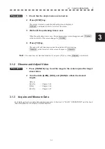
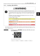
3.4.7 Rain/Snow Clutter Suppression[RAIN]
When using the [SEA] function, never set the suppression level too high
canceling out all image noises from the sea surface at close range.
Detection of not only echoes from waves but also targets such as other ships
or dangerous objects will become inhibited.
When using the [SEA] function, make sure to choose the most appropriate
image noise suppression level.
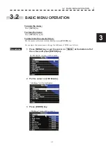
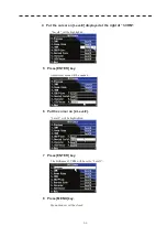
Procedures
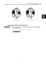
1 Adjust the rain/snow clutter returns of the display by turning the
[RAIN] dial until targets can be easily observed.
Turning
[RAIN]
dial clockwise suppresses rain/snow clutter returns.
Turning
[RAIN]
dial counterclockwise intensifies rain/snow clutter returns.
When the
[RAIN]
dial control is turned clockwise, the rain/snow clutter suppression function
suppresses rain/snow clutter returns and gets targets hidden by rain/snow clutter returns to
appear on the radar display.
However, be careful that excessive suppression may cause small targets to be overlooked.
Since the rain/snow clutter suppression function also has the effect of suppressing sea clutter,
the suppression efficiency improves when the
[RAIN]
dial is used with the
[SEA]
dial.
In general, turn the
[RAIN]
dial fully to the left.
3.4.8 Interference Rejection [IR]
Interference by other radars is rejected.
z
When viewing a radar beacon or SART signal, select
IR Off (Interference Rejection Off) because IR
processing suppresses the video.
Attention
Summary of Contents for JMR-611
Page 2: ......
Page 24: ......
Page 26: ......
Page 28: ......
Page 33: ...1 5 1 1 4 EXTERIOR DRAWINGS y Fig 1 1 Exterior Drawing of Scanner Unit Type NKE 387 Unit mm...
Page 34: ...1 6 Fig 1 2 Exterior Drawing of Processing Unit Type NDC 1774 Unit mm...
Page 35: ...1 7 1 1 4 EXTERIOR DRAWINGS y Fig 1 3 Exterior Drawing of Operating Unit Type NCE 5923 Unit mm...
Page 38: ......
Page 54: ......
Page 116: ......
Page 118: ......
Page 124: ......
Page 134: ......
Page 136: ......
Page 142: ......
Page 144: ......
Page 154: ......
Page 156: ......
Page 160: ......
Page 164: ......
Page 166: ......
Page 172: ......
Page 174: ......
Page 177: ...APPENDIX Fig 1 Block Diagram of JMR 611...
Page 181: ...APPENDIX Fig 5 Internal Connection Diagram of Control Unit NCM 994...
Page 182: ......
Page 184: ......
Page 186: ......
Page 187: ......