2-6
0.Previous
1.AIS Function
Off/On
2.AIS Symbol Display
Off/On
3.Vector
Off/5sec/10sec/20sec/30sec/60sec/120sec/1
80sec/240sec/300sec
4.Special AIS Symbols
Off/On
5.AIS Integration
5.Date/Time
Setting >
䊻
0.Previous
1.Time Zone Setting
2.Local Date
3.Local Time
6.Own Mark >
䊻
0.Previous
1.Filled
Off/On
2.Radar Targets On Top
Off/On
3.Profile >
䊻
0.Previous
1.Own Ship
Off/Rectangle
/Pentagon
2.2nd Ship
Off/Rectangle
/Pentagon
3.3rd Ship
䊻
1. Profile
Off/Rectangle
/Pentagon
2. Dimension
Beam
Lemgth
3. Position
a
b
4.4th Ship
䊻
1. Profile
Off/Rectangle
/Pentagon
2. Dimension
Beam
Lemgth
3. Position
a
b
5.5th Ship
䊻
1. Profile
Off/Rectangle
/Pentagon
2. Dimension
Beam
Lemgth
3. Position
a
b
6.6th Ship
䊻
1. Profile
Off/Rectangle
/Pentagon
2. Dimension
Beam
Lemgth
3. Position
a
b
7.7th Ship
䊻
1. Profile
Off/Rectangle
/Pentagon
2. Dimension
Beam
Lemgth
3. Position
a
b
8.Next
䊼
Next
4.AIS Settings >
Summary of Contents for JMR-611
Page 2: ......
Page 24: ......
Page 26: ......
Page 28: ......
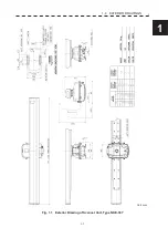
Page 33: ...1 5 1 1 4 EXTERIOR DRAWINGS y Fig 1 1 Exterior Drawing of Scanner Unit Type NKE 387 Unit mm...
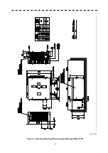
Page 34: ...1 6 Fig 1 2 Exterior Drawing of Processing Unit Type NDC 1774 Unit mm...
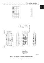
Page 35: ...1 7 1 1 4 EXTERIOR DRAWINGS y Fig 1 3 Exterior Drawing of Operating Unit Type NCE 5923 Unit mm...
Page 38: ......
Page 54: ......
Page 116: ......
Page 118: ......
Page 124: ......
Page 134: ......
Page 136: ......
Page 142: ......
Page 144: ......
Page 154: ......
Page 156: ......
Page 160: ......
Page 164: ......
Page 166: ......
Page 172: ......
Page 174: ......
Page 177: ...APPENDIX Fig 1 Block Diagram of JMR 611...
Page 181: ...APPENDIX Fig 5 Internal Connection Diagram of Control Unit NCM 994...
Page 182: ......
Page 184: ......
Page 186: ......
Page 187: ......

