3-20
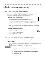
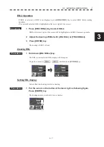
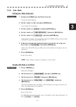
3.5.5 Move Own Ship’s Display Position [OFF CENT]
The own ship’s position can be moved from the display center to stern or bow direction.
Procedures
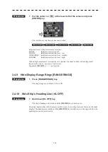
1 Press [OFF CENT] key.
The display at the lower right of the screen (Fig.2.3-
ն
) will be changed.
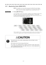
The own ship’s position will be moved from the display center as following each time the
[OFF CENT] key is pressed:
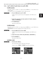
3.5.6 Display Other Ships’ Trails [TRAILS]
Other ships’ movements and speeds can be monitored from the lengths and directions of their trails, serving for
collision avoidance.
Procedures
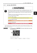
1 Put the cursor on TRAILS at the lower left of the screen and press
[ENTER] key .
Trails length will be changed as following sequence .
Trails length will be switched as following each time
TRAILS
is pressed.
OFF
2Scan
15sec
30sec
1min
2min
3min
4min
5min
6min
OFF
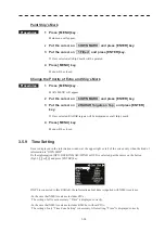
Erasing Trails Data
Procedures
1 Put the cursor on TRAILS and hold down more than 2seconds.
All the stored trails data will be erased.
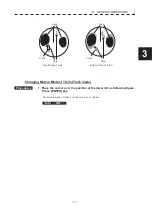
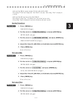
Trails Motion Mode
There are two types of trails: relative motion trails and true motion trails.
Relative motion trails: The system plots the trails of a target at a position relative to the own ship.
The operator can easily judge whether the target is approaching the own
ship.
While the own ship is moving, the system also plots the trails of land and
other fixed targets.
True motion trails:
The system plots the absolute motion trails of a target, irrespective of the
own ship’s position.
The operator can easily judge the course and speed of the target.
The system does not plot the trails of land and other fixed targets.
NOTE
:
Accurate true bearing signals and speed signals are necessary for using the true
motion trails mode.
60% of display radius
in the stern direction
40% of display radius
in the stern direction
On center
20% of display radius
in the stern direction
center 1
center 2
off
center 3
Summary of Contents for JMR-611
Page 2: ......
Page 24: ......
Page 26: ......
Page 28: ......
Page 33: ...1 5 1 1 4 EXTERIOR DRAWINGS y Fig 1 1 Exterior Drawing of Scanner Unit Type NKE 387 Unit mm...
Page 34: ...1 6 Fig 1 2 Exterior Drawing of Processing Unit Type NDC 1774 Unit mm...
Page 35: ...1 7 1 1 4 EXTERIOR DRAWINGS y Fig 1 3 Exterior Drawing of Operating Unit Type NCE 5923 Unit mm...
Page 38: ......
Page 54: ......
Page 116: ......
Page 118: ......
Page 124: ......
Page 134: ......
Page 136: ......
Page 142: ......
Page 144: ......
Page 154: ......
Page 156: ......
Page 160: ......
Page 164: ......
Page 166: ......
Page 172: ......
Page 174: ......
Page 177: ...APPENDIX Fig 1 Block Diagram of JMR 611...
Page 181: ...APPENDIX Fig 5 Internal Connection Diagram of Control Unit NCM 994...
Page 182: ......
Page 184: ......
Page 186: ......
Page 187: ......

