5.5 DISPLAY OF RADAR TRANSPONDER
yy
yyy
5-9
5
5.5
DISPLAY OF RADAR TRANSPONDER
(SART)
The SART (Search and rescue Radar Transponder) is a survival device authorized by the GMDSS (Global
Maritime Distress and Safety System), which is used for locating survivors in case that a distress accident
occurs at sea. The SART is designed to operate in the 9 GHz frequency band.
When receiving the 9 GHz radar signal (interrogating signal) transmitted from the radar equipment on a rescue
ship or search aircraft, the SART transmit a series of response signals to inform the distress position to the
rescue and search party.
The setting for SART signal reception
(1) Sea clutter control:
Minimum (Most counterclockwise)
(2) Rain and Snow Clutter Control (RAIN):
Minimum (Most counterclockwise)
(3) TUNE control:
No tuning (to weaken clutter echoes)
(4) Interference rejecter (IR):
OFF
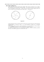
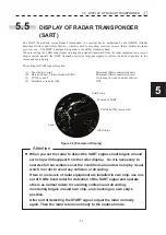
Figure 5.8 [Example of Display]
SART code
Position of SART
Position of the rescue craft
Other ships
Land
z
When you set the radar to detect the SART signal, small targets around
own ship will disappear from the radar display. So it is necessary to
exercise full surveillance over the conditions around own ship by visual
watch in order to avoid any collision or stranding.
If two or more sets of radar equipment are installed in own ship, use one
set of 9 GHz band radar for detection of the SART signal and operate
others as normal radars for avoiding collision and stranding,
monitoring targets around own ship, and checking on own ship’s
position.
After end of detecting the START signal, adjust the radar normally
again. Then the radar returns normally to the nautical mode.
Attention
Summary of Contents for JMR-611
Page 2: ......
Page 24: ......
Page 26: ......
Page 28: ......
Page 33: ...1 5 1 1 4 EXTERIOR DRAWINGS y Fig 1 1 Exterior Drawing of Scanner Unit Type NKE 387 Unit mm...
Page 34: ...1 6 Fig 1 2 Exterior Drawing of Processing Unit Type NDC 1774 Unit mm...
Page 35: ...1 7 1 1 4 EXTERIOR DRAWINGS y Fig 1 3 Exterior Drawing of Operating Unit Type NCE 5923 Unit mm...
Page 38: ......
Page 54: ......
Page 116: ......
Page 118: ......
Page 124: ......
Page 134: ......
Page 136: ......
Page 142: ......
Page 144: ......
Page 154: ......
Page 156: ......
Page 160: ......
Page 164: ......
Page 166: ......
Page 172: ......
Page 174: ......
Page 177: ...APPENDIX Fig 1 Block Diagram of JMR 611...
Page 181: ...APPENDIX Fig 5 Internal Connection Diagram of Control Unit NCM 994...
Page 182: ......
Page 184: ......
Page 186: ......
Page 187: ......

