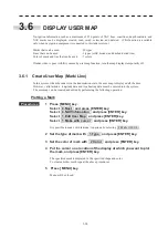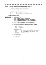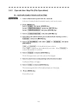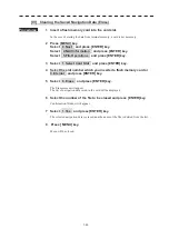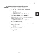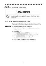
3.6 DISPLAY USER MAP
y
yy
3-33
3
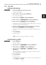
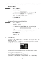
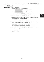
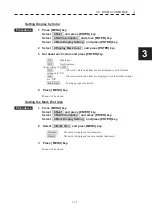
Setting Display by Color
Procedures
1 Press [MENU] key.
Select 8.Next and press [ENTER] key.
Select 4.NAV Information and press [ENTER] key.
Select 4.Mark Display Setting and press [ENTER] key.
2 Select 2.Display Mark Color and press [ENTER] key.
3 Set about each colors and press [ENTER] key.
On
: Displayed.
Off
: Not Displayed.
About setting of All ,
Off
: All color’s marks and lines are not displayed even if all other
settings are “On”.
On
: All color’s marks and lines are displayed even if all other settings
are “Off”.
Individual
: Setting by type is activated.
4 Press [ MENU] key.
Menu will be closed.
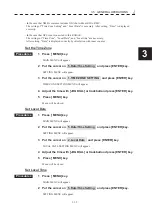
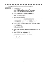
Setting the Mark Font Size
Procedures
1 Press [MENU] key.
Select 8.Next and press [ENTER] key.
Select 4.NAV Information and press [ENTER] key.
Select 4.Mark Display Setting and press [ENTER] key.
2 Select 3.Mark Size and press [MENU] key.
Normal
: The mark is displayed in normal size.
Small
: The mark is displayed in a size smaller than usual.
3 Press [ MENU] key.
Menu will be closed.
Summary of Contents for JMR-611
Page 2: ......
Page 24: ......
Page 26: ......
Page 28: ......
Page 33: ...1 5 1 1 4 EXTERIOR DRAWINGS y Fig 1 1 Exterior Drawing of Scanner Unit Type NKE 387 Unit mm...
Page 34: ...1 6 Fig 1 2 Exterior Drawing of Processing Unit Type NDC 1774 Unit mm...
Page 35: ...1 7 1 1 4 EXTERIOR DRAWINGS y Fig 1 3 Exterior Drawing of Operating Unit Type NCE 5923 Unit mm...
Page 38: ......
Page 54: ......
Page 116: ......
Page 118: ......
Page 124: ......
Page 134: ......
Page 136: ......
Page 142: ......
Page 144: ......
Page 154: ......
Page 156: ......
Page 160: ......
Page 164: ......
Page 166: ......
Page 172: ......
Page 174: ......
Page 177: ...APPENDIX Fig 1 Block Diagram of JMR 611...
Page 181: ...APPENDIX Fig 5 Internal Connection Diagram of Control Unit NCM 994...
Page 182: ......
Page 184: ......
Page 186: ......
Page 187: ......

