3-18
3.5.3 Use VRMs (Variable Range Markers) [VRM1/VRM2]
This function is to display and select variable range markers (VRMs). Two VRMs are available: VRM1 is
represented as a broken line, and VRM2 as a dotted line.
VRM1 Operation
If VRM2 is selected or VRM1 is not displayed, press
[VRM1/VRM2]
key to select VRM1 before
starting operation.
(The currently selected VRM is highlighted at the lower right of the screen.)
Procedures
1 Press [VRM1/VRM2] key to select VRM1.
VRM1 at the lower right of the screen will be highlighted, and VRM1 becomes operable.
2 Adjust the range of VRM1 with [JOG DIAL] or [TRACKBALL].
3 Press [ENTER] key .
The range of VRM1 is fixed .
VRM2 Operation
If VRM1 is selected or VRM2 is not displayed, press
[VRM1/VRM2]
key to select VRM2 before
starting operation.
(The currently selected VRM is highlighted at the lower right of the screen.)
Procedures
1 Press [VRM1/VRM2] key to select VRM2.
VRM2 at the lower right of the screen will be highlighted, and VRM2 becomes operable.
2 Adjust the range of VRM2 with [JOG DIAL] or [TRACKBALL].
3 Press [ENTER] key .
The range of VRM2 is fixed.
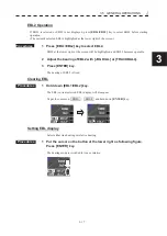
Clearing VRM
Procedures
1 Hold down [VRM1/VRM2] key.
The VRM (current selected VRM) display will disappear.
Or put the cursor on VRM1 / VRML2 and hold down
[ENTER]
key.
Summary of Contents for JMR-611
Page 2: ......
Page 24: ......
Page 26: ......
Page 28: ......
Page 33: ...1 5 1 1 4 EXTERIOR DRAWINGS y Fig 1 1 Exterior Drawing of Scanner Unit Type NKE 387 Unit mm...
Page 34: ...1 6 Fig 1 2 Exterior Drawing of Processing Unit Type NDC 1774 Unit mm...
Page 35: ...1 7 1 1 4 EXTERIOR DRAWINGS y Fig 1 3 Exterior Drawing of Operating Unit Type NCE 5923 Unit mm...
Page 38: ......
Page 54: ......
Page 116: ......
Page 118: ......
Page 124: ......
Page 134: ......
Page 136: ......
Page 142: ......
Page 144: ......
Page 154: ......
Page 156: ......
Page 160: ......
Page 164: ......
Page 166: ......
Page 172: ......
Page 174: ......
Page 177: ...APPENDIX Fig 1 Block Diagram of JMR 611...
Page 181: ...APPENDIX Fig 5 Internal Connection Diagram of Control Unit NCM 994...
Page 182: ......
Page 184: ......
Page 186: ......
Page 187: ......

