10.1 JMR-611 TYPE RADAR
yy
yyyy
yyyy
10-1
10
10.1
JMR-611
TYPE
RADAR
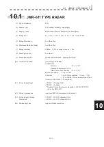
(1) Type of Emission
P0N
(2) Display type
PPI method, vertically long display
(3) Display panel
Radar video effective diameter of 270mm (min)
(4) Range Scale
0.1, 0.2, 0.3, 0.4, 0.5, 0.8, 1.2, 1.6, 2, 4, 8, 16 and 32km
(5) Range Resolution
Less than 15m
(6) Minimum Detective Range
Less than 15m
(7) Range Accuracy
Within
s
1.5% of range in use or
s
5m
(8) Bearing Accuracy
Less than 1
r
(9) Bearing Indication
Relative Motion mode: Head-up/North-up
(10) Ambient Condition
According to IEC60945
Temperature
Scanner:
-25 to +55
Υ
(Storage
Tempe70
Υ
)
Other Unit except Scanner: -15 to +55
Υ
Relative Humidity
93% at +40
Υ
Vibration
2 to 13.2Hz, amplitude
s
1mm
s
10%
13.2 to 100Hz, Gravity acceleration 0.7m/s
2
Velocity of the wind 27.8m/s(54kt)
(11) Power Supply Input
+24VDC (Display Unit)
+24VDC
(Scanner)
* Display Unit and Scanner correspond to 100VAC/220VAC
when use NBA-5111.
(12) Power Consumption
Approx. 400W (In maximum wind velocity)
(13) Power Supply Voltage
+24VDC –10/+30% (Display Unit)
Fluctuation
+24VDC –10/+30% (Scanner Unit)
(14) Pre-heating Time
Approx. Within 1min30sec
Summary of Contents for JMR-611
Page 2: ......
Page 24: ......
Page 26: ......
Page 28: ......
Page 33: ...1 5 1 1 4 EXTERIOR DRAWINGS y Fig 1 1 Exterior Drawing of Scanner Unit Type NKE 387 Unit mm...
Page 34: ...1 6 Fig 1 2 Exterior Drawing of Processing Unit Type NDC 1774 Unit mm...
Page 35: ...1 7 1 1 4 EXTERIOR DRAWINGS y Fig 1 3 Exterior Drawing of Operating Unit Type NCE 5923 Unit mm...
Page 38: ......
Page 54: ......
Page 116: ......
Page 118: ......
Page 124: ......
Page 134: ......
Page 136: ......
Page 142: ......
Page 144: ......
Page 154: ......
Page 156: ......
Page 160: ......
Page 164: ......
Page 166: ......
Page 172: ......
Page 174: ......
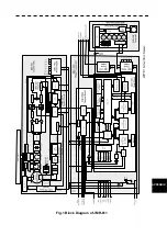
Page 177: ...APPENDIX Fig 1 Block Diagram of JMR 611...
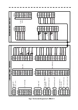
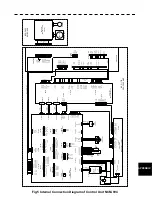
Page 181: ...APPENDIX Fig 5 Internal Connection Diagram of Control Unit NCM 994...
Page 182: ......
Page 184: ......
Page 186: ......
Page 187: ......

