5-6
5.4
FALSE
ECHOES
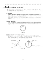
The radar observer may be embarrassed with some echoes that do not exist actually. These false echoes
appear by the following causes that are well known:
[I] Shadow
When the radar scanner is installed near a funnel or mast, the echo of a target that exists in the direction of
the funnel or mast cannot appear on the radar display because the radar beam is reflected on the funnel or
mast. Whether there are some false echoes due to shadows can be checked monitoring the sea clutter
returns, in which there may be a part of weak or no returns.
Such shadows appear always in the same directions, which the operator should have in mind in radar
operation.
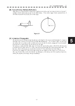
[II] Side Lobe Effect
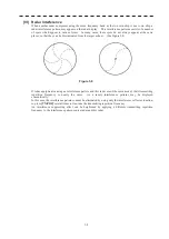
A broken-line circular arc may appear at the same range as the main lobe of the radar beam on the radar
display. This type of false echo can easily be discriminated when a target echo appears isolated. (See
Figure 5.5)
Figure 5.5
[III] False Echo by Secondary Reflection
When a target exists near own ship, two echoes from the single target may appear on the radar display.
One of those echoes is the direct echo return from the target and the other is the secondary reflection return
from a mast or funnel that stands in the same direction as shown in Figure 5.6.
Figure 5.6
Direct microwave
Radar scanner
Funnel
Actual target
Secondary reflection
of microwave
False echo from funnel
Summary of Contents for JMR-611
Page 2: ......
Page 24: ......
Page 26: ......
Page 28: ......
Page 33: ...1 5 1 1 4 EXTERIOR DRAWINGS y Fig 1 1 Exterior Drawing of Scanner Unit Type NKE 387 Unit mm...
Page 34: ...1 6 Fig 1 2 Exterior Drawing of Processing Unit Type NDC 1774 Unit mm...
Page 35: ...1 7 1 1 4 EXTERIOR DRAWINGS y Fig 1 3 Exterior Drawing of Operating Unit Type NCE 5923 Unit mm...
Page 38: ......
Page 54: ......
Page 116: ......
Page 118: ......
Page 124: ......
Page 134: ......
Page 136: ......
Page 142: ......
Page 144: ......
Page 154: ......
Page 156: ......
Page 160: ......
Page 164: ......
Page 166: ......
Page 172: ......
Page 174: ......
Page 177: ...APPENDIX Fig 1 Block Diagram of JMR 611...
Page 181: ...APPENDIX Fig 5 Internal Connection Diagram of Control Unit NCM 994...
Page 182: ......
Page 184: ......
Page 186: ......
Page 187: ......


