xvi
Glossary
Anti-clutter rain (FTC)
: Rain/snow clutter suppression.
Anti-clutter sea (STC)
: Sea clutter suppression.
AZI MODE (Azimuth Stabilization MODE)
:
Bearing
display
mode.
BRG :
Bearing.
COG (Course Over Ground)
: Course relative to the ground.
CUP (Course-Up)
: Own ship’s course is pointed to the top center of the radar
display.
EBL (Electronic Bearing Line)
: An electronic bearing line originated from own ship’s position.
ENH (Enhance)
: A target can be enlarged.
GND
: Stabilization relative to the ground.
GPS (Global Positioning System)
: The position of a GPS receiver can be determined by the signals
from GPS satellites.
HDG (Heading)
: Own ship’s heading bearing. The display ranges from 000 to 360
degrees as scanned clockwise.
HL (Heading Line)
: Ship’s heading line.
HUP (Head-Up)
: Own ship’s heading line is always pointed to the top center of the
radar display.
IR (Interference Rejector) : Radar interference rejector.
MRK (Mark)
: Reflection plot.
NM (Nautical Mile)
: 1NM = 1852m.
NUP (North-Up)
: The north is always pointed to the top center of the radar display.
PIN
: Information set by the user (personal code).
RCS (Radar Cross Section)
: Radar reflection sectional area.
Relative Vector
: A target’s movement predicted relative to own ship.
RM (Relative Motion)
: Relative motion presentation. Own ship’s position is fixed and
other targets move relative to own ship.
RR (Range Rings)
: Fixed range ring.
SCANNER :
Antenna.
Summary of Contents for JMR-611
Page 2: ......
Page 24: ......
Page 26: ......
Page 28: ......
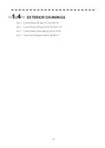
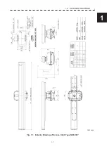
Page 33: ...1 5 1 1 4 EXTERIOR DRAWINGS y Fig 1 1 Exterior Drawing of Scanner Unit Type NKE 387 Unit mm...
Page 34: ...1 6 Fig 1 2 Exterior Drawing of Processing Unit Type NDC 1774 Unit mm...
Page 35: ...1 7 1 1 4 EXTERIOR DRAWINGS y Fig 1 3 Exterior Drawing of Operating Unit Type NCE 5923 Unit mm...
Page 38: ......
Page 54: ......
Page 116: ......
Page 118: ......
Page 124: ......
Page 134: ......
Page 136: ......
Page 142: ......
Page 144: ......
Page 154: ......
Page 156: ......
Page 160: ......
Page 164: ......
Page 166: ......
Page 172: ......
Page 174: ......
Page 177: ...APPENDIX Fig 1 Block Diagram of JMR 611...
Page 181: ...APPENDIX Fig 5 Internal Connection Diagram of Control Unit NCM 994...
Page 182: ......
Page 184: ......
Page 186: ......
Page 187: ......

