2-8
䊼
8.next
1.Screen Capure
Setting
䚷䠚
䊻
0.Previous
1.Select Card Slot
Slot1/Slot2
2.Save File
3.Erase File
4.Capture Mode
Off/Manual/AUTO-1/AUTO-2
5.AUTO Capture Interval
1
䡚
999min
䠄
Auto-1
䠅
15
䡚
999sec
䠄
Auto-2
䠅
6.AUTO
䚷
File
䚷
Erase
Off/On
2.User Setting >
䊻
0.Previous
1.Load User Setting
2.Save User Setting
3.Erase User Setting
3.Format Card
䚷䠚䊻
0.Previous
1.Select Card Slot
Slot1/Slot2
2.Format
4.NAV
Information >
䊻
0.Previous
1.Edit User Map
䊻
0.Previous
1.Make with Cursor
䊻
0.Previous
1.Type
䠄
Mark/Line
䠅
2.Color
White/Cyan/Blue
/Green/Yellow
/Pink/Red
2.Make with L/L
䊻
0.Previous
1.Type
䠄
Mark/Line
䠅
2.Color
White/Cyan/Blue
/Green/Yellow
/Pink/Red
3.L/L
4.Enter
5.New Line Input
䋽
New Mark Input
3.Move
4.Delete
5.Insert/Move Vertex
6.Delete Vertex
7.DEL by Type/Color
Type
䠖
ALL or each
Color :
ALL/White/Cyan/
Blue/Green/
Yellow/Pink/Red
8.Remeain Point
2.Shift
3.Shift Clear
䊻
0.Previous
䊻
0.Previous
1.All
Off/On/
Individual
2.
䕿
Off/On
3.
䕧
Off/On
4.
䕱
Off/On
5.
䕕
Off/On
6.
䕻
Off/On
7. Wreck 1
Off/On
8.Next
4.Mark Display Setting >
1.Display Mark Type >
Summary of Contents for JMR-611
Page 2: ......
Page 24: ......
Page 26: ......
Page 28: ......
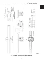
Page 33: ...1 5 1 1 4 EXTERIOR DRAWINGS y Fig 1 1 Exterior Drawing of Scanner Unit Type NKE 387 Unit mm...
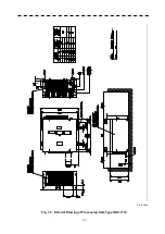
Page 34: ...1 6 Fig 1 2 Exterior Drawing of Processing Unit Type NDC 1774 Unit mm...
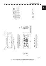
Page 35: ...1 7 1 1 4 EXTERIOR DRAWINGS y Fig 1 3 Exterior Drawing of Operating Unit Type NCE 5923 Unit mm...
Page 38: ......
Page 54: ......
Page 116: ......
Page 118: ......
Page 124: ......
Page 134: ......
Page 136: ......
Page 142: ......
Page 144: ......
Page 154: ......
Page 156: ......
Page 160: ......
Page 164: ......
Page 166: ......
Page 172: ......
Page 174: ......
Page 177: ...APPENDIX Fig 1 Block Diagram of JMR 611...
Page 181: ...APPENDIX Fig 5 Internal Connection Diagram of Control Unit NCM 994...
Page 182: ......
Page 184: ......
Page 186: ......
Page 187: ......

