1-1
1
1.1 FUNCTIONS
y
1.1
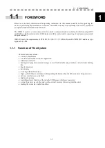
FOREWORD
Please read the safety information and operating instructions in this manual carefully before operating the
device or performing any maintenance work on it. Your radar will only work optimally if the correct procedures
for operation and maintenance are followed.
The JMR-611 series is a color radar system. It consists a scanner unit and a control unit which can output DVI
and RGB to a high-resolution color LCD display unit. (The control unit is consisting of a radar process unit and
an operation unit.)
JMR-611 meets the requirements of ETSI EN 302 194-1 V1.1.2 (2006-10) and ES-TRIN 2019 and has a type
approval e-01-024.
1.1.1 Function of This System
The main functions include:
x
sensitivity adjustment
x
sea clutter and rain/snow clutter suppression
x
interference reflector
x
bearing and range measurement using a cursor, fixed/variable range markers, and electronic bearing
line
x
targets expansion
x
trails display
x
receiving inland AIS sentence
x
display of AIS label (vessel name) while pushing the button when the AIS sentence is being received
x
delivery of echo’s screen by LAN
x
display of user map
x
controlling almost function of the radar by USB mouse which user connected
x
saving the radar screen to the inside or the external memory (Screen capture function)
x
making the own mark coupled condition
Summary of Contents for JMR-611
Page 2: ......
Page 24: ......
Page 26: ......
Page 28: ......
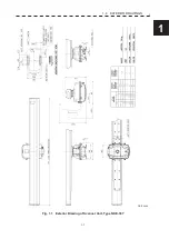
Page 33: ...1 5 1 1 4 EXTERIOR DRAWINGS y Fig 1 1 Exterior Drawing of Scanner Unit Type NKE 387 Unit mm...
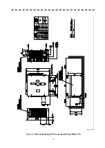
Page 34: ...1 6 Fig 1 2 Exterior Drawing of Processing Unit Type NDC 1774 Unit mm...
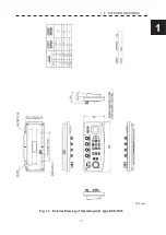
Page 35: ...1 7 1 1 4 EXTERIOR DRAWINGS y Fig 1 3 Exterior Drawing of Operating Unit Type NCE 5923 Unit mm...
Page 38: ......
Page 54: ......
Page 116: ......
Page 118: ......
Page 124: ......
Page 134: ......
Page 136: ......
Page 142: ......
Page 144: ......
Page 154: ......
Page 156: ......
Page 160: ......
Page 164: ......
Page 166: ......
Page 172: ......
Page 174: ......
Page 177: ...APPENDIX Fig 1 Block Diagram of JMR 611...
Page 181: ...APPENDIX Fig 5 Internal Connection Diagram of Control Unit NCM 994...
Page 182: ......
Page 184: ......
Page 186: ......
Page 187: ......

