3.3 PREPARATION
y
yy
3-9
3
3.3.6 Reset Alarm Buzzer [ALARM ACK]
When an audible alarm is issued, use
[ALARM ACK]
to acknowledge the alarm information, stop the alarm
buzzing, and stop the alarm lamp flashing. (If more than one alarm has occurred, press the switch for each
alarm indication.) The alarm stops buzzing, but the alarm indication does not disappear.
Procedures
1 Press [ALARM ACK] key.
The alarm will stop buzzing.
3.3.7 Set Display Color
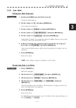
Color can be changed for each item of information (shown below) on the screen by operating the menu.
1.ECHO
Change the colors of radar echoes.
2.TRAILS
Change the colors of radar trails.
3.ECHO BACK GROUND
Change the background color inside the bearing scale.
4.DATA BACK GROUND
Change the background color outside the bearing scale.
5.ROT BAR
Change the colors of ROT bar.
6.PILOT
Change the colors of the symbol of pilot.
7.RUDDER BAR
Change the colors of rudder bar.
8.OTHERS
Change the colors of characters etc.
9. OWN MARK
Change the colors of own ship mark.
10.AIS/VECTOR
Change the colors of the symbol of AIS and own ship’s vector.
11.VRM
Change the colors of VRM.
Procedures
1 Press [MENU] key .
Put the cursor on [2.COLOR] and press [ENTER] key.
The color-setting menu will appear.
2 Put the cursor on the item to be changed and press [ENTER] key.
The kinds of color menu will appear.
Select the color to be set, and press [ENTER] key.
The selected color will be set.
Exit
1 Press [MENU] key.
The menu will be closed.
Note:
The display color set here are saved in accordance with the day/night mode.
Summary of Contents for JMR-611
Page 2: ......
Page 24: ......
Page 26: ......
Page 28: ......
Page 33: ...1 5 1 1 4 EXTERIOR DRAWINGS y Fig 1 1 Exterior Drawing of Scanner Unit Type NKE 387 Unit mm...
Page 34: ...1 6 Fig 1 2 Exterior Drawing of Processing Unit Type NDC 1774 Unit mm...
Page 35: ...1 7 1 1 4 EXTERIOR DRAWINGS y Fig 1 3 Exterior Drawing of Operating Unit Type NCE 5923 Unit mm...
Page 38: ......
Page 54: ......
Page 116: ......
Page 118: ......
Page 124: ......
Page 134: ......
Page 136: ......
Page 142: ......
Page 144: ......
Page 154: ......
Page 156: ......
Page 160: ......
Page 164: ......
Page 166: ......
Page 172: ......
Page 174: ......
Page 177: ...APPENDIX Fig 1 Block Diagram of JMR 611...
Page 181: ...APPENDIX Fig 5 Internal Connection Diagram of Control Unit NCM 994...
Page 182: ......
Page 184: ......
Page 186: ......
Page 187: ......


