


2-1
2.1 NAMES AND FUNCTIONS OF CONTROL PANEL SWITCHES
yy
2
FIG 2.1 DISPLAY & READOUTS
Rate of Turn Indicator
Auto Pilot Indicator
Rudder Indicator
PPI Range Scale
Range Marker Interval
Trail Display Time
Target Expansion Level
(OFF/Fair/Strong)
MENU
Screen Capture
Screen Capture Mode
Display Color Mode
ALARM
Tune Indicator
Center Position Select
Bearing Mode Indicator
Interference Rejecter
Level
SEA STATE Mode
Video Noise Rejection Indicator
TX Pulse Width
Transmit/Standby Indicator
Auto Tuning
Cursor Position
(Azimuth Range)
VRM 1/2 Range
EBL 1/2 Bearing
P-LINE 1/2 Range
Rain Volume Position
Sea Volume Position
Gain Volume Position
Depth or SOG Display
Depth or SOG
Numeric Display
Depth or SOG Display
Depth or SOG Numeric Display
Menu Select
Menu Select
Echo Border
AIS Information
Summary of Contents for JMR-611
Page 2: ......
Page 24: ......
Page 26: ......
Page 28: ......
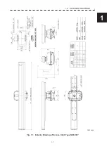
Page 33: ...1 5 1 1 4 EXTERIOR DRAWINGS y Fig 1 1 Exterior Drawing of Scanner Unit Type NKE 387 Unit mm...
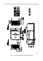
Page 34: ...1 6 Fig 1 2 Exterior Drawing of Processing Unit Type NDC 1774 Unit mm...
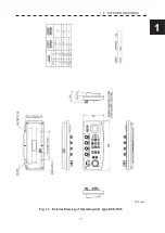
Page 35: ...1 7 1 1 4 EXTERIOR DRAWINGS y Fig 1 3 Exterior Drawing of Operating Unit Type NCE 5923 Unit mm...
Page 38: ......
Page 54: ......
Page 116: ......
Page 118: ......
Page 124: ......
Page 134: ......
Page 136: ......
Page 142: ......
Page 144: ......
Page 154: ......
Page 156: ......
Page 160: ......
Page 164: ......
Page 166: ......
Page 172: ......
Page 174: ......
Page 177: ...APPENDIX Fig 1 Block Diagram of JMR 611...
Page 181: ...APPENDIX Fig 5 Internal Connection Diagram of Control Unit NCM 994...
Page 182: ......
Page 184: ......
Page 186: ......
Page 187: ......