Operating Procedures:
Optimising an Image
5-11
the cursor around the screen to achieve maximum sharpness.
When you are satisfied, release the mouse button.
3. The
MUI
(optional): adjust image sharpness with the stigmator
X
and
Y
knobs until the best image is achieved. The computer beeps
when the stigmator limits are reached.
6.
Repeat steps 1–5 as necessary.
If astigmatism is severe and the cross is close to the edge of the
screen when nearing correction, release the mouse button and
reposition the cross in the centre of the screen. Then repeat the
procedure above to perform further astigmatism correction. You can
use reduced area advantageously (see Chapter 4).
If an astigmatism cannot be corrected, there may be some other reason,
usually the final lens aperture is dirty (see Chapter 8), the magnification
may be too high for the beam spot size (see below) or the sample is
charging (apply conductive layer or use the LoVac / ESEM mode).
PRESSURE AND WORKING DISTANCE (WD)
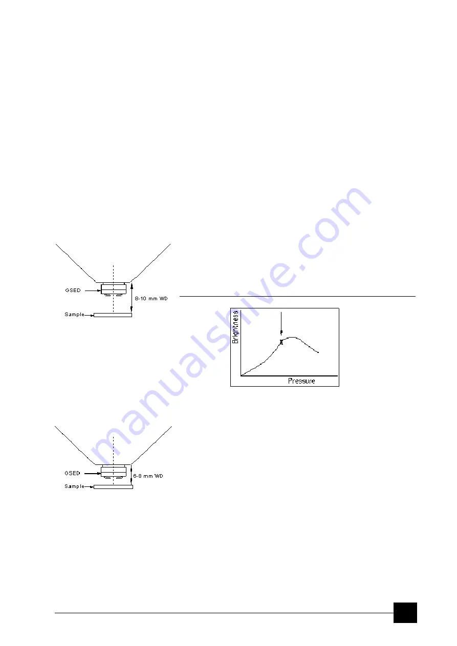
It is assumed the LoVac / ESEM mode is set, the GSED or GBSD is
installed and the sample is visible in the image display area.
For
standard imaging
choose the highest specimen point and bring it
to the 10 mm WD (the yellow line in an optical quad). Focus the image
and then
link Z to FWD
. Adjust the chamber pressure to achieve the
brightest possible image. Lower the pressure about 67 Pa (0.5 Torr)
from this point.
FIGURE 5-2
BRIGHTNESS VS PRESSURE
Adjust contrast and brightness to personal taste to obtain a clear,
optimized image, which should allow small changes (about 0.5 mm) in
WD without the need to alter the chamber pressure.
High resolution imaging
is achieved by moving the sample closer to
the pole piece; the objective lens performs the better the smaller is the
WD. Adjust the chamber pressure (see above, the pressure should be
a little higher).
Note:
Some experimentation may be necessary, as the relationship between
WD and chamber pressure is largely sample-dependent.
Caution:
Always take care when moving the stage up because of possible lens
pole contact.
Summary of Contents for Quanta FEG 250
Page 8: ...C vi...
Page 28: ...System Operation Quanta FEG System States 3 10...
Page 108: ...Alignments 1 Gun Alignment 6 6...
Page 114: ...Alignments 154 Water Bottle Venting 6 12 154 Water Bottle Venting...
Page 152: ...System Options Automatic Aperture System 9 4...
Page 154: ...System Options Nav Cam 9 6 401 NAV CAM AUTOBRIGHTNESS...
Page 177: ...System Options Cooling Stage Waterless Cooling Stage 9 29...


