Operating Procedures:
Optimising an Image
5-9
CONTRAST AND BRIGHTNESS
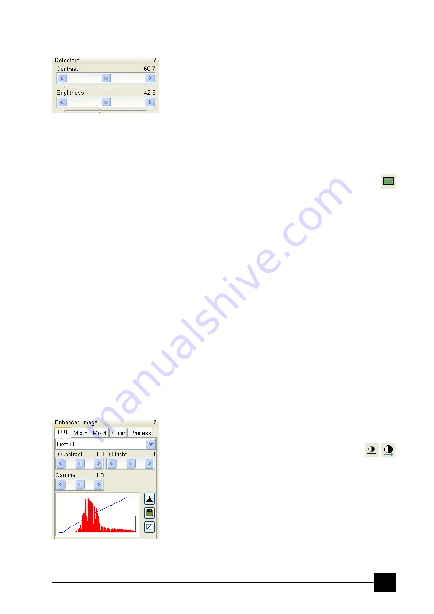
The contrast and brightness can be set manually either by adjusting
the
Detectors
module controls (see Chapter 4) or using the MUI
(option). Follow the procedure:
1.
Select a medium speed scan in an active quad.
2.
Reduce the contrast to zero and adjust the brightness to a level so
that the last gray level can be seen, by eye, before the screen goes
black.
3.
Increase the contrast so that the signal level shows an image.
4.
If necessary, adjust the brightness level to improve the image.
These adjusters always have a label / editable value (displaying the
actual Contrast or Brightness level in %) in the upper left / right corner.
Using Videoscope (F3)
This mode could facilitate contrast and brightness optimization to
obtain full greyscale level range of an image.
Three yellow horizontal lines (placed over the image window) indicate
white (top line), grey (middle line) and black (bottom line) levels. The
oscillogram signal amplitude / central position reflects a contrast /
brightness of the just scanned line. If the oscillogram is cut by the
bottom / top line, the signal level is clipped in black / white. This should
be avoided because the image details are lost in the clipped areas.
Tuning the oscillogram exactly between the top and bottom lines for a
feature of interest (with the use of the reduced area) results in the full
detailed image. The signal clipping may be used to obtain harder
contrast conditions when more black and white is needed. The signal
amplitude lowering decreases the contrast, i.e. the image looks softer.
Follow the procedure:
1.
Select a slow scan in an active quad.
2.
Activate the Videoscope (
F3
/ toolbar icon /
Scan
menu).
3.
Reduce the contrast to zero and adjust the brightness level to the
lower dashed line (black).
4.
Increase the contrast so that the signal level just clips the upper
dashed line (white).
5.
If necessary, adjust the brightness level once more so that the
average signal level is roughly in the middle.
6.
The high and low peaks should just clip the dashed lines.
Enhanced Image
module can be used to adjust the LUT, including
Gamma control. This can be useful for low signal conditions or odd
imaging requirements. Results affect the videoscope display.
Note:
Use also the following functions to optimize
the Contrast / Brightness (see Chapter 4):
Auto Contrast Brightness
(F9),
User Auto Contrast Brightness
,
Display Saturation
(Shift +
F11).
Summary of Contents for Quanta FEG 250
Page 8: ...C vi...
Page 28: ...System Operation Quanta FEG System States 3 10...
Page 108: ...Alignments 1 Gun Alignment 6 6...
Page 114: ...Alignments 154 Water Bottle Venting 6 12 154 Water Bottle Venting...
Page 152: ...System Options Automatic Aperture System 9 4...
Page 154: ...System Options Nav Cam 9 6 401 NAV CAM AUTOBRIGHTNESS...
Page 177: ...System Options Cooling Stage Waterless Cooling Stage 9 29...


