Chapter XVIOscilloscope Probe (Option)
219
16.14.2 Operating Instructions
When the AP204A current probe is used, the input impedance of the oscilloscope is set to 1M
Ω
, the probe type is
set to current, and the probe attenuation is set to the same as that of the AP204A.
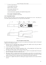
Test card slot
Card slot upper
cover
Sliding switch
Demagnetizing
key
Probe body
Power supply
interface
Output BNC
Power indicator
Balance knob
Fig. 16.31 Diagram of AP204A Probe
The AP204A current probe is easy to use, but users who are not familiar with this product should read this manual
completely before starting the operation:
1
)
Make sure the input power supply voltage of the power adapter is normal before use.
2
)
In order to obtain accurate measurement results in different test cases, demagnetization and DC balance
adjustment should be performed before the test. The specific steps are as follows:
Warm up the oscilloscope for 20 minutes and set the vertical offset of the oscilloscope channel for
connecting the probe to zero
Connect the output BNC of the current probe to the input end of zeroing channel of the oscilloscope
Keep the test card slot of the current probe empty and toggle the sliding switch on the card slot upper
cover to ensure that the upper cover is well closed
Press the demagnetizing button and adjust the balance knob to make the display signal zero
3
)
Slide the sliding switch on the card slot upper cover backward, open the test card slot upper cover, put the
test conductor into the test card slot, push the sliding switch and close the card slot upper cover. The test
conductor shall be not powered on in this process.
4
)
Power on the conductor, adjust the oscilloscope settings as needed, and read the measurement result. When
the measurement result is positive, it means that the current flowing through the conductor is in the same
direction as the arrow indicated on the upper cover of the test card slot.
5
)
After the test is completed, disconnect the conductor power supply and then take out the conductor from the
card slot.
Summary of Contents for 4456 Series
Page 10: ...VIII...
Page 55: ...Chapter V Trigger System 45 Fig 5 51 RF Test Signal Example...
Page 69: ...Chapter VII Mathematical Operation 59 Fig 7 10 Advanced Math Example...
Page 71: ...Chapter VIII Display System 61 Fig 8 3 Wfm Palette Menu Fig 8 4 Normal Palette...
Page 72: ...Chapter VIII Display System 62 Fig 8 5 Inverted Palette Fig 8 6 Temperature Palette...
Page 75: ...Chapter VIII Display System 65 Fig 8 12 XY Display Example...
Page 165: ...Chapter XI Protocol Analyzer Option 155 Fig 11 242 1553 Trigger and Analysis Example...


