Chapter XIX Application Examples
244
screen. Click the menu key [High] and turn the Multipurpose b to set the high threshold. Click the menu key
[Low] and turn the Multipurpose b to set the low threshold. Or click the menu key [Choose Preset] to pop up
the Level3 Menu of the preset type selection on the left side of the menu and turn the Multipurpose b to
select the preset threshold and then press the Multipurpose b to select the corresponding preset type or
directly click the corresponding type for selection on the screen.
7)
Click the menu key [Bus Display] to pop up the 1553 bus display setup menu on the right side of the screen,
click the menu key [Display] to pop up the Level3 Menu of the bus display mode on the left side of the menu,
turn the Multipurpose b to select the bus and waveform display mode and then press the Multipurpose b to
confirm Select, or set directly by clicking the Bus and Waveforms option in the Level3 Menu; click the menu
key [Number Format] to pop up the Level3 Menu of the number format setting on the left side of the menu,
turn the Multipurpose b to select Hex and then press the Multipurpose b to confirm Select, or directly set by
clicking the Hex option in the Level3 Menu; click the menu key [Bus Offset] and turn the Multipurpose b to
change the position of the bus in the vertical direction of the display area; click the menu key [Waveforms
Offset] and turn the Multipurpose b to change the position of the digital waveform in the vertical direction of
the display area;
8)
Press the
【
Trigger
】
key in the Function Area on the front panel to pop up the trigger setup menu on the
lower screen, click the menu key [Type] to pop up the trigger type selection menu on the right side of the
screen, and click the menu key [Bus] to select the protocol trigger mode;
9)
Click the menu key [Trigger On] at the bottom of the screen to pop up the 1553 protocol trigger type setup
menu on the right side of the screen, and click the menu key [Sync] to set the 1553 protocol trigger type to
Sync.
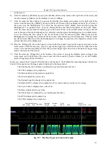
The 1553 bus decoding trigger is displayed in the figure below:
The Frame Start of the 1553 bus is indicated by a green left square bracket [.
The Sync, Send Bit, Word Count, and Parity Check are displayed in purple boxes.
The RTA Address and Sub Address are displayed in yellow boxes.
The Stop is indicated by a red right square bracket].
Frame
Start
Sync
RTA
Address
Send
Bit
Sub
Address
Word
Count
Parity
Check
Frame
End
Fig. 19.12 1553 Trigger and Analysis Example
Summary of Contents for 4456 Series
Page 10: ...VIII...
Page 55: ...Chapter V Trigger System 45 Fig 5 51 RF Test Signal Example...
Page 69: ...Chapter VII Mathematical Operation 59 Fig 7 10 Advanced Math Example...
Page 71: ...Chapter VIII Display System 61 Fig 8 3 Wfm Palette Menu Fig 8 4 Normal Palette...
Page 72: ...Chapter VIII Display System 62 Fig 8 5 Inverted Palette Fig 8 6 Temperature Palette...
Page 75: ...Chapter VIII Display System 65 Fig 8 12 XY Display Example...
Page 165: ...Chapter XI Protocol Analyzer Option 155 Fig 11 242 1553 Trigger and Analysis Example...


