Chapter III Vertical System
14
Click [Termination] menu key, and the channel input impedance can be switched between 1 MΩ and 50Ω. In
addition, 1 MΩ or 50Ω is displayed in the corresponding channel status bar.
Attention: The input impedance will also be automatically identified after the probe is automatically identified, so
no input impedance setting is required.
3.6
Bandwidth
Set the bandwidth limit to reduce the display noise. For example, the measured signal is a signal with a HF
component.
If selecting [Full], the HF component of the measured signal can pass through.
If [20M] or [250M] is selected, the HF component larger than 20 MHz or 250 MHz of the measured
signal will be blocked.
When any channel key CH1 ~ CH4 is pressed down, open the channel menu for bandwidth limit setting of the
channel.
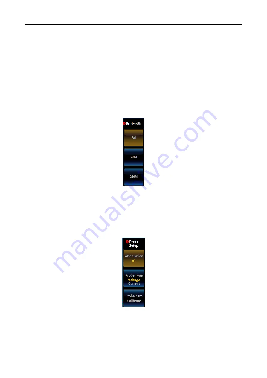
Click [Bandwidth] menu key, and the Bandwidth option will be displayed on the right side of the screen:
Fig. 3.7 Bandwidth Menu
Click the corresponding key, and the corresponding Bandwidth option can be set.
3.7
Probe Setup
It can be used for the probe attenuation coefficient and probe type setup as well as probe zero.
When any channel key CH1 ~ CH4 is pressed down, open the channel menu for probe setup.
Click [Probe Setup] menu key, and the Probe Setup option will be displayed on the right side of the screen:
Fig. 3.8 Probe Setup Menu
3.7.1 Attenuation
Click [Attenuation] menu key, and the Attenuation option at the left side of the button will pop up.
The Attenuation option of the voltage and current probe is:
Summary of Contents for 4456 Series
Page 10: ...VIII...
Page 55: ...Chapter V Trigger System 45 Fig 5 51 RF Test Signal Example...
Page 69: ...Chapter VII Mathematical Operation 59 Fig 7 10 Advanced Math Example...
Page 71: ...Chapter VIII Display System 61 Fig 8 3 Wfm Palette Menu Fig 8 4 Normal Palette...
Page 72: ...Chapter VIII Display System 62 Fig 8 5 Inverted Palette Fig 8 6 Temperature Palette...
Page 75: ...Chapter VIII Display System 65 Fig 8 12 XY Display Example...
Page 165: ...Chapter XI Protocol Analyzer Option 155 Fig 11 242 1553 Trigger and Analysis Example...


