Chapter XI Protocol Analyzer (Option)
60
Chapter XI Protocol Analyzer (Option)
The 4456 series oscilloscope supplies a powerful set of serial protocol analysis tools, which support auto trigger
and analysis of many buses like I2C, SPI, CAN, LIN, FlexRay, RS232, USB, Audio and 1553, provide serial bus
test solutions of embedded, auto, computer, audio and other serial protocols. Based on FPGA hardware decoding
technique, the 4456 series oscilloscope improves the acquisition probability of random serial communication error
codes.
Table 11.1 Protocol Analysis
Protocol
Analysis
Decode channel
1
Display format
Binary, hexadecimal
Display
Bus, digital, event list with time scale information.
I2C (option S04)
Signal rate:
≤
10Mbps
Protocol type: 7 digits/10 digits address
RS232 (option S05)
Signal rate: 50bps~2Mbps
SPI (option S06)
Signal rate:
≤
10Mbps
CAN (option S07)
Signal rate: 10kbps~1Mbps
LIN (option S08)
Signal rate: 800bps~100kbps
Protocol standard: 1.x, 2.x
FlexRay (option S09)
Signal rate: 2.5Mbps
、
5Mbps
、
10Mbps
Audio (option S10)
Signal rate:
≤
10Mbps
Protocol standard: I2S, LJ, RJ, TDM
USB (option S11)
Signal rate: Low speed 1.5 Mbps, full speed 12 Mbps
1553 (option S12)
Signal rate: 1Mbps
11.1
I2C trigger and analysis
The I2C bus includes SCLK (clock) and SDA (data) lines. The I2C bus frame structure is composed of start,
address, data, ACK and stop, which can be triggered on start, repeat start, stop, ACK loss, address, data, address
and data.
Start Bit
Address
(7 Bits or
10 Bits)
R/W
(
1Bit
)
Ack Bit
(1Bit)
Data0
(8Bits)
Ack Bit0
(1Bit)
Data1
(8Bit)
Ack1
(1Bit)
„„
DataN
(8Bits)
Ack N
(1Bit)
Stop Bit
Fig. 11.1 I2C Frame Format
11.1.1 I2C bus setting
Press down
【
Bus
】
key in the Function Area on the front panel, and the Bus setup menu will pop up on the lower
screen:
Fig. 11.2 Bus Setup Menu
Click [Bus] menu key, and the Bus Type selection menu will pop up on the right side of the screen:
Summary of Contents for 4456 Series
Page 10: ...VIII...
Page 55: ...Chapter V Trigger System 45 Fig 5 51 RF Test Signal Example...
Page 69: ...Chapter VII Mathematical Operation 59 Fig 7 10 Advanced Math Example...
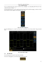
Page 71: ...Chapter VIII Display System 61 Fig 8 3 Wfm Palette Menu Fig 8 4 Normal Palette...
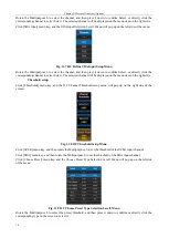
Page 72: ...Chapter VIII Display System 62 Fig 8 5 Inverted Palette Fig 8 6 Temperature Palette...
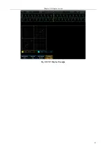
Page 75: ...Chapter VIII Display System 65 Fig 8 12 XY Display Example...
Page 165: ...Chapter XI Protocol Analyzer Option 155 Fig 11 242 1553 Trigger and Analysis Example...


