Chapter XIII Power Measurement and Analysis (Option)
169
13.7
Safe Operating Area
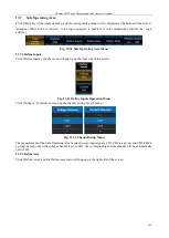
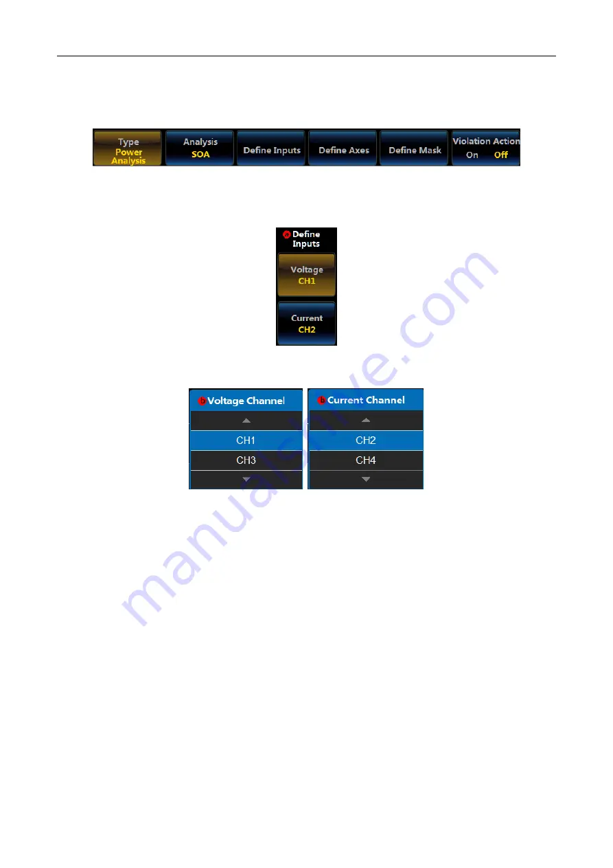
Click [SOA] key of the Analysis menu, and the corresponding menu will be displayed at the bottom of the screen:
Attention: When SOA is selected, if the logic analyzer is enabled, it will automatically disable the logic
analyzer.
Fig. 13.30 Safe Operating Area Menu
13.7.1 Define Inputs
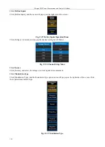
Click [Define Inputs], and the menu will pop up on the right side of the screen:
Fig. 13.31 Define Inputs Operation Menu
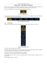
Click [Voltage] / [Current], and pop up the channel setting Level3 Menu:
Fig. 13.32 Channel Setup Menu
The measurement of the Safe Operating Area needs two-way input signals, CH1/CH2 is a group, and CH3/CH4 is
a group, namely, when the voltage channel is set to CH1, the corresponding current channel will be automatically
set to CH2.
13.7.2 Define Axes
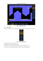
Click [Define Axes], and the Define Axes menu will pop up on the right side of the screen:
Summary of Contents for 4456 Series
Page 10: ...VIII...
Page 55: ...Chapter V Trigger System 45 Fig 5 51 RF Test Signal Example...
Page 69: ...Chapter VII Mathematical Operation 59 Fig 7 10 Advanced Math Example...
Page 71: ...Chapter VIII Display System 61 Fig 8 3 Wfm Palette Menu Fig 8 4 Normal Palette...
Page 72: ...Chapter VIII Display System 62 Fig 8 5 Inverted Palette Fig 8 6 Temperature Palette...
Page 75: ...Chapter VIII Display System 65 Fig 8 12 XY Display Example...
Page 165: ...Chapter XI Protocol Analyzer Option 155 Fig 11 242 1553 Trigger and Analysis Example...


