Chapter XVIOscilloscope Probe (Option)
206
voltage
600Vrms CATIII
Noise
1/50:
≤
1.5mVrms
1/500:
≤
1mVrms
Linearity
±1%
Delay
20ns±1ns
CMRR
DC:
≥
80dB
100Hz:
≥
60dB
1MHz:
≥
50dB
Over-range alarm voltage threshold
1/50: 140V ± 4V (DC + ACpeak)
1/500: 1400V ± 40V (DC + ACpeak)
Power adapter output voltage
DC9V, 1000mA
Power adapter input voltage
AC100 ~ 240V, 50 ~ 60Hz
Probe body
120×55×24 (mm)
Weight
160g
Environmental characteristics
Operating temperature
0 ~ 40°C
Storage temperature
-10 ~ 45
℃
16.9
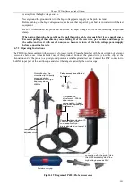
P8100 High Voltage Differential Probe
The P8100 high voltage differential probe uses a differential input mode and is mainly used for places where high
voltage floating measurements are required. The probe has a bandwidth of 100MHz and is available with 1/50 and
1/500 attenuations. Its differential mode measurement range is 130V (DC + peak AC) and 1300V (DC + peak AC).
The probe has the function of over-range alarm with a red LED. The option can be purchased by users. The option
number is 4456-H06.
16.9.1 Instructions for Safe Use
The P8100 high voltage differential probe uses a differential input mode and is mainly used for places where high
voltage floating measurements are required. To ensure the safety of users and the product and the equipment
connected to the product, you shall strictly observe the following safety operation specifications:
Use correct power adapter: You must use the original power adapter of this product to avoid damage to
the probe.
Master and use correct connection and disconnection methods: When connecting, connect the probe
output to the test instrument and then connect the probe input; connect the test input auxiliary accessory
and then connect the input circuit. When disconnecting, disconnect the test input and then disconnect the
probe output end.
Grounding: This product is connected to the earth of the oscilloscope through the BNC output terminal.
It is necessary to ensure reliable grounding during use.
Pay attention to the input measurement voltage range to avoid exceeding the range. Use 1/500
attenuation when the measured voltage cannot be estimated and must be measured. When the over-range
warning light illuminates, stop using it immediately and disconnect the power supply and the input
voltage.
Do not use this product and its accessories with the product case open. Non-professionals do not open
the casing of this product and its accessories.
Do not use the instrument in flammable or explosive environments.
Do not use the instrument in too humid environments.
16.9.2 Operating Instructions
Summary of Contents for 4456 Series
Page 10: ...VIII...
Page 55: ...Chapter V Trigger System 45 Fig 5 51 RF Test Signal Example...
Page 69: ...Chapter VII Mathematical Operation 59 Fig 7 10 Advanced Math Example...
Page 71: ...Chapter VIII Display System 61 Fig 8 3 Wfm Palette Menu Fig 8 4 Normal Palette...
Page 72: ...Chapter VIII Display System 62 Fig 8 5 Inverted Palette Fig 8 6 Temperature Palette...
Page 75: ...Chapter VIII Display System 65 Fig 8 12 XY Display Example...
Page 165: ...Chapter XI Protocol Analyzer Option 155 Fig 11 242 1553 Trigger and Analysis Example...


