Chapter XVIOscilloscope Probe (Option)
205
4
)
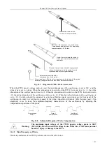
The power adapter is connected to the probe and the green power (POWER) indicator lights up.
5
)
Select the appropriate range for the probe based on the measured voltage. When the measured voltage
exceeds the range during test, the red overload (OVER RANGE) indicator will light up and at this time the
power supply and the input should be disconnected immediately.
6
)
Set the attenuation ratio of the oscilloscope or other instruments based on the probe range. After starting the
measurement, set the appropriate sensitivity of the oscilloscope according to the size of the measured signal.
7
)
Connect the measured object to start measurement. Upon measuring, the probe body should be kept away
from the high voltage pulse circuit to reduce errors caused by interference.
8
)
After the completion of the test, disconnect the probe power supply, disconnect the two input ends from the
measured point and then unplug the input BNC terminal from the oscilloscope.
Tips for use of P8050 high voltage differential probe:
1
)
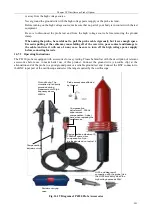
The input line should be winded during measurement, which can better eliminate noise and improve
high-frequency response capability. The winding method is as shown below:
Fig. 16.23 Diagram of P8050 Probe Winding Method
2
)
Do not extend the input line during measurement, otherwise this will introduce more noise. If the input line
must be extended, the lengths of the extensions should be the same. Moreover, the frequency of the measured
input signal should not exceed 10 MHz at this time. If the frequency exceeds 10 MHz, the error will be big.
3
)
To obtain high-precision measurement results, the measurement shall be made after the probe and the
measuring instrument are warmed up for 20 minutes.
Warning:
The maximum input voltage of the P8050 high voltage differential probe is
1300V (DC+ACpp). Do not exceed this voltage in use. Otherwise, it will cause
personal hazard or injury or damage to the DUTs.
16.8.3 Main Parameters of Probe
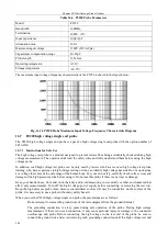
The main parameters of the P8050 probe are shown in the table below.
Table 16.8 P8050 Probe Parameters
Model
P8050
Bandwidth (-3dB)
50MHz
Rise time
7ns
Precision
± 2%
Attenuation ratio
1/50, 1/500
Termination
Between two input ends: 8MΩ
Input capacitance
Between two input ends: 3.5pF
Maximum differential measurement
voltage
1/50: 130V (DC + ACpeak)
1/500: 1300V (DC + ACpeak)
Maximum common mode input 1000Vrms CATII
Summary of Contents for 4456 Series
Page 10: ...VIII...
Page 55: ...Chapter V Trigger System 45 Fig 5 51 RF Test Signal Example...
Page 69: ...Chapter VII Mathematical Operation 59 Fig 7 10 Advanced Math Example...
Page 71: ...Chapter VIII Display System 61 Fig 8 3 Wfm Palette Menu Fig 8 4 Normal Palette...
Page 72: ...Chapter VIII Display System 62 Fig 8 5 Inverted Palette Fig 8 6 Temperature Palette...
Page 75: ...Chapter VIII Display System 65 Fig 8 12 XY Display Example...
Page 165: ...Chapter XI Protocol Analyzer Option 155 Fig 11 242 1553 Trigger and Analysis Example...


