Chapter V Trigger System
26
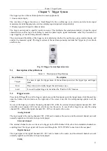
Click the corresponding option button to set the trigger coupling mode.
Auxiliary channel
When the
“
Auxiliary Channel
”
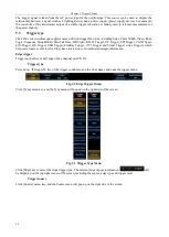
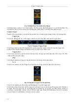
is selected as the trigger source, click [Configure Aux Channel] key of the trigger
menu, and the Configure Aux Channel menu will pop up on the right side of the screen.
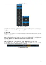
Fig. 5.6 Configure Aux Channel Menu
The corresponding probe attenuation coefficient can be set according to the attenuation multiplier of the probe of
the connected auxiliary channel signal. The settable probe coefficient is the same as the probe coefficient in the
channel, which isx1 ~ x5000.
The attenuation multiplier of the connected auxiliary channel signal can be selected according to the size of the
connected external channel signal. Settable options: ÷1,
10.
Pulse trigger
Trigger on a positive or negative pulse of the specified width of the input signal.
Trigger type
Press down
【
Trigger
】
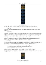
key of the trigger control area on the front panel, and open the trigger menu.
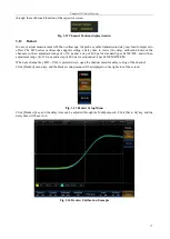
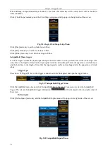
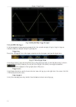
Fig. 5.7 Pulse Trigger Menu
Click [Type] menu key and click [Pulse Width] key in the popup Type menu to select the pulse width trigger. The
relevant pulse width trigger information
will be displayed on the top right corner of the screen,
including the source, polarity and trigger level.
Trigger source
Click [Source] menu key, and the Source menu will pop up on the right side of the screen. The CH1
CH4 can be
made as the source.
Polarity
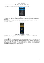
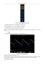
Click [Polarity] menu key, and trigger on a positive or negative pulse of the specified width of the input signal.
Trigger When
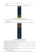
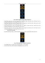
Click [Trigger When] menu key, and the Trigger When setup menu will pop up on the right side of the screen:
Summary of Contents for 4456 Series
Page 10: ...VIII...
Page 55: ...Chapter V Trigger System 45 Fig 5 51 RF Test Signal Example...
Page 69: ...Chapter VII Mathematical Operation 59 Fig 7 10 Advanced Math Example...
Page 71: ...Chapter VIII Display System 61 Fig 8 3 Wfm Palette Menu Fig 8 4 Normal Palette...
Page 72: ...Chapter VIII Display System 62 Fig 8 5 Inverted Palette Fig 8 6 Temperature Palette...
Page 75: ...Chapter VIII Display System 65 Fig 8 12 XY Display Example...
Page 165: ...Chapter XI Protocol Analyzer Option 155 Fig 11 242 1553 Trigger and Analysis Example...


