Chapter XVIOscilloscope Probe (Option)
211
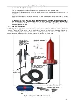
BP-266N: High voltage dedicated IC clamp
Power adapter
Input end
Power indicator
Output end
Overload
indicator
Attenuation ratio
selection
External power supply
end
BP-250: Double-ended
BNC test cable
BP-276N: High
pressure dedicated
crocodile clip
BP-366: Banana head
high voltage cable
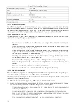
Fig. 16.26 Diagram of P5020 Probe
Warning:
The maximum input voltage of the P5020 high voltage differential probe is 40kV
(DC+ACpp). Do not exceed this voltage when using it. Otherwise, it will cause
personal hazard or injury or damage to the DUTs.
16.10.3 Main Parameters of Probe
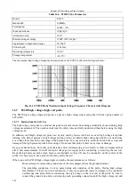
The main parameters of the P5020 probe are shown in the table below.
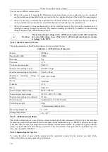
Table 16.10 P5020 Probe Parameters
Model
P5020
Bandwidth (-3dB)
20MHz
Precision
± 2%
Attenuation ratio
1/500, 1/5000
Termination
Between two input ends: 100MΩ
Input capacitance
Between two input ends: 1pF
Maximum differential measurement
voltage
1/500: 4kV (DC+ACpp)
1/5000: 40kV (DC+ACpp)
CMRR
60Hz: > 80dB
100Hz: > 60dB
Summary of Contents for 4456 Series
Page 10: ...VIII...
Page 55: ...Chapter V Trigger System 45 Fig 5 51 RF Test Signal Example...
Page 69: ...Chapter VII Mathematical Operation 59 Fig 7 10 Advanced Math Example...
Page 71: ...Chapter VIII Display System 61 Fig 8 3 Wfm Palette Menu Fig 8 4 Normal Palette...
Page 72: ...Chapter VIII Display System 62 Fig 8 5 Inverted Palette Fig 8 6 Temperature Palette...
Page 75: ...Chapter VIII Display System 65 Fig 8 12 XY Display Example...
Page 165: ...Chapter XI Protocol Analyzer Option 155 Fig 11 242 1553 Trigger and Analysis Example...


