Chapter XVIOscilloscope Probe (Option)
220
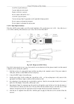
Tips for use of AP204A current probe:
1
)
When it is necessary to measure the differential current waveforms of two conductors, the two conductors
can be simultaneously inserted into the test card slot in the opposite direction of the current for measurement.
2
)
When it is necessary to measure the superimposed current waveforms of two conductors, the two conductors
can be parallelly inserted into the test card slot in the same current direction for measurement.
3
)
When it is necessary to increase the sensitivity due to small test current, the wires can be winded for a few
turns before passing through the card slot. The measured reading is divided by the number of wires passing
through the card slot to obtain the desired result.
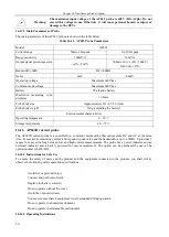
Warning:
The maximum input voltage of the AP202 current probe is 40A (DC+ACpk). Do
not exceed this voltage in use. Otherwise, it will cause personal hazard or injury
or damage to the DUTs.
16.14.3 Main Parameters of Probe
The main parameters of the AP204A probe are shown in the table below.
Table 16.14 AP204A Probe Parameters
Model
AP204A
Bandwidth (-3dB)
50MHz
Rise time
7ns
Precision
± 3%
Current conversion ratio
50mV/A
Maximum measuring current
20A(DC+ACpk)
Maximum measuring pulse current
50A (Tp
≤
10μs)
Maximum measuring voltage to
ground
400V (DC+ACpk)
Noise
≤
1mVrms
Linearity
± 1%
Delay
20ns±1ns
Power adapter output voltage
DC9V, 1000mA
Power adapter input voltage
AC100 ~ 240V, 50 ~ 60Hz
Maximum measuring wire diameter
4.5mm
Probe body size
Approximately 188×40×24 (mm)
Probe body weight
150g
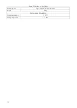
Environmental characteristics
Operating temperature
0 ~ 40°C
Storage temperature
-10 ~ 45
℃
16.15 AP622 Current Probe
The AP622 current probe is a cost-effective, common current probe that can measure DC and AC at the same time.
Its measuring current ranges from 50mA to 60A peak and the bandwidth is up to 100kHz. It provides two ranges
(10A and 100A) for easy switching between low and high current measurements. The probe has a power indicator
and an overload indicator and is battery powered for easy measurement. The option can be purchased by users.
The option number is 4456-H07.
16.15.1 Instructions for Safe Use
To ensure the safety of users and the product and the equipment connected to the product, you shall strictly
observe the following safety operation specifications:
Summary of Contents for 4456 Series
Page 10: ...VIII...
Page 55: ...Chapter V Trigger System 45 Fig 5 51 RF Test Signal Example...
Page 69: ...Chapter VII Mathematical Operation 59 Fig 7 10 Advanced Math Example...
Page 71: ...Chapter VIII Display System 61 Fig 8 3 Wfm Palette Menu Fig 8 4 Normal Palette...
Page 72: ...Chapter VIII Display System 62 Fig 8 5 Inverted Palette Fig 8 6 Temperature Palette...
Page 75: ...Chapter VIII Display System 65 Fig 8 12 XY Display Example...
Page 165: ...Chapter XI Protocol Analyzer Option 155 Fig 11 242 1553 Trigger and Analysis Example...


