Chapter V Trigger System
23
Chapter V Trigger System
The trigger system of the oscilloscope has two main applications:
1. Ensure stable display
The invention of trigger function is a breakthrough for the oscilloscope as an electric and electronic signal
measurement and debugging tool, and it can display repeated periodical signal stably.
2. Display signals with specific characteristics
The trigger can respond to specific waveform events. This facilitates the isolation and display of specific signal
characteristics, such as logic level failing to reach the pulse height, signal interference caused by crosstalk, low
edge triggering, or invalid timing between channels.
The precision and flexibility of the trigger system determine whether the oscilloscope can accurately display and
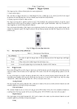
analyze the measured signal. The trigger system of the oscilloscope mainly includes the Trigger key, Level knob
and Force key.
Fig. 5.1 Trigger System Operation Area
5.1
Description of Keys/Buttons
Table 5.1 Description of Keys/Buttons
Keys/Buttons
Description
Trigger
It is used to open the trigger menu of the oscilloscope and set the trigger type and trigger
mode.
Force
Press it down to forcedly trigger the oscilloscope once.
Level
It is used to adjust trigger level and has the
“
Push for 50%
”
function.
5.2
Trigger source
Press down
【
Trigger
】
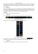
key of the trigger control area on the front panel, open the trigger menu, click [Source] key,
open the Source selection menu on the right side of the screen, and click the corresponding options to set the
source.
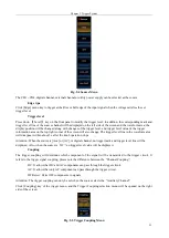
In case of the Edge type, besides the analog channel CH1
CH4, the external channel, digital channels D0 ~ D15
and utility power supply (AC Line) can also be used as the source. In case of other trigger type, only the analog
channel CH1
CH4 or the digital channels D0 ~ D15 can be used as the source.
Analog channel
The input signal of the analog channels CH1
CH4 can be made as the source, and the selected channel can work
normally regardless of whether its input is displayed.
External channel
The external channel source can be used to trigger on the fifth channel while other four simulation channels are
acquiring data. The trigger signal will be accessed through the
“
AUX IN
”
BNC connector on the rear panel.
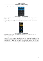
Digital channel
The input signal of the digital channels D0 ~ D15 can be made as the source, and the selected channel can work
normally regardless of whether its input is displayed.
Utility
Summary of Contents for 4456 Series
Page 10: ...VIII...
Page 55: ...Chapter V Trigger System 45 Fig 5 51 RF Test Signal Example...
Page 69: ...Chapter VII Mathematical Operation 59 Fig 7 10 Advanced Math Example...
Page 71: ...Chapter VIII Display System 61 Fig 8 3 Wfm Palette Menu Fig 8 4 Normal Palette...
Page 72: ...Chapter VIII Display System 62 Fig 8 5 Inverted Palette Fig 8 6 Temperature Palette...
Page 75: ...Chapter VIII Display System 65 Fig 8 12 XY Display Example...
Page 165: ...Chapter XI Protocol Analyzer Option 155 Fig 11 242 1553 Trigger and Analysis Example...


