Chapter II About the 4456 Series Digital Phosphor Oscilloscope
10
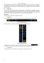
The Trigger System Setup Area is composed of the Trigger Key, Level Key and Force Key.
1)
【
Trigger
】
: It is used to set the trigger system of the oscilloscope, including functions covering the trigger
type, trigger source, trigger polarity, trigger mode, trigger sensitivity and trigger holdoff.
2)
【
Level
】
: It is used to set the level of the oscilloscope. Rotate the knob to make the level of the trigger
channel to move up or down; press it down to set the level to 50%.
3)
【
Force
】
: It is a kind of software trigger mode. When the channel signal is not normally triggered and the
Force key is pressed down, the waveform will be triggered once.
2.2.12 Vertical System Setup Area
Fig. 2.15 Vertical System Setup Area
The Vertical System Setup Area is composed of the Channel Keys, Position Knob and Scale Knob, and setup
methods of 4 channels are the same.
1)
【
1
】
: It is used to set the vertical system of the Channel1 of the oscilloscope, including the channel switch,
input impedance, bandwidth limit, channel delay and probe setting.
2)
【
2
】
: It is used to set the vertical system of the Channel2 of the oscilloscope, including the channel switch,
input impedance, bandwidth limit, channel delay and probe setting.
3)
【
3
】
: It is used to set the vertical system of the Channel3 of the oscilloscope, including the channel switch,
input impedance, bandwidth limit, channel delay and probe setting.
4)
【
4
】
: It is used to set the vertical system of the Channel4 of the oscilloscope, including the channel switch,
input impedance, bandwidth limit, channel delay and probe setting.
5)
【
Position
】
: It is used to set the vertical offset of the CH1 ~ CH4 of the oscilloscope. Rotate it, and the
vertical offset of the CH1 ~ CH4 will move up or down; press it down, and the position will be set to 0.
6)
【
Scale
】
: It is used to set the vertical scope of the CH1 ~ CH4 of the oscilloscope. Rotate it, and the vertical
sensitivity of the CH1 ~ CH4 will be increased or decreased by one gear according to the step.
2.2.13 Input Channels Area
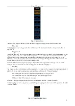
Fig. 2.16 Input Channels Area
2.3
Overview of rear panel
The rear panel of the 4456 series digital phosphor oscilloscope is as shown in 0, including the AUX IN, AUX
OUT, 10 MHz IN/OUT, LAN, VIDEO OUT, USB DEVICE, USB HOST and POWER INPUT Ports.
Summary of Contents for 4456 Series
Page 10: ...VIII...
Page 55: ...Chapter V Trigger System 45 Fig 5 51 RF Test Signal Example...
Page 69: ...Chapter VII Mathematical Operation 59 Fig 7 10 Advanced Math Example...
Page 71: ...Chapter VIII Display System 61 Fig 8 3 Wfm Palette Menu Fig 8 4 Normal Palette...
Page 72: ...Chapter VIII Display System 62 Fig 8 5 Inverted Palette Fig 8 6 Temperature Palette...
Page 75: ...Chapter VIII Display System 65 Fig 8 12 XY Display Example...
Page 165: ...Chapter XI Protocol Analyzer Option 155 Fig 11 242 1553 Trigger and Analysis Example...


