Chapter XVIOscilloscope Probe (Option)
189
Chapter XVI Oscilloscope Probe (Option)
The 4456 series oscilloscope supports passive voltage probe, high voltage single end probe, high voltage
differential probe, current probe and logic probe to satisfy the test requirements of probe in different cases.
16.1
P9350A passive voltage probe
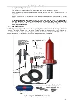
As a passive single end probe, the P9350A passive voltage probe has a bandwidth of 350 MHz, fixed attenuation
of 10:1 and input impedance of 10 M
Ω
, which supports automatic identification functions. It is a standard probe
of 4456C/CM, which can be purchased by users. The option number is 4456-H14.
16.1.1 Operating Instructions
The P9350A probe is equipped with accessories for easy testing. Please be familiar with the description of
relevant accessories before use to make better use of this product.
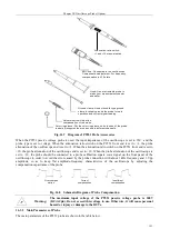
Probe front end:
Fully enclosed design for
safer use
BNC end: Connected to the oscilloscope
Compensation adjustment: For frequency
compensation in X10 state
Hook: Use a retractable probe to
make your measurements easier
and safer
Ground clamp: Use a crocodile-type ground
clamp to reliably ground the probe for safe
operation and correct signal reading
Adjustment rod: Adjust the
compensation of the probe
Color ring sleeve: Put the color ring sleeve on both ends of the probe
to easily distinguish the probes used in different channels
Automatic identification end:
Automatically identify the
probe and set the impedance
of the oscilloscope and the
probe attenuation
Fig. 16.1 Diagram of P9350A Probe Accessories
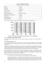
When the P9350A passive voltage probe is used, the input impedance of the oscilloscope is automatically set to
1M
Ω
, the probe type is automatically set to voltage, and the probe attenuation is automatically set to ×10. To
avoid the error caused by the probe connection, the probe should be connected to a probe calibration square wave
signal on the front panel of the oscilloscope, with about 1 kHz frequency and 3 Vpp amplitude, so as to keep flat
amplitude-frequency characteristics of the oscilloscope by adjusting the compensation capacitance of the probe.
Fig. 16.2 Schematic Diagram of Probe Compensation
Over-compen
sation
Correct
compensation
Insufficient
compensation
Summary of Contents for 4456 Series
Page 10: ...VIII...
Page 55: ...Chapter V Trigger System 45 Fig 5 51 RF Test Signal Example...
Page 69: ...Chapter VII Mathematical Operation 59 Fig 7 10 Advanced Math Example...
Page 71: ...Chapter VIII Display System 61 Fig 8 3 Wfm Palette Menu Fig 8 4 Normal Palette...
Page 72: ...Chapter VIII Display System 62 Fig 8 5 Inverted Palette Fig 8 6 Temperature Palette...
Page 75: ...Chapter VIII Display System 65 Fig 8 12 XY Display Example...
Page 165: ...Chapter XI Protocol Analyzer Option 155 Fig 11 242 1553 Trigger and Analysis Example...


