Chapter XI Protocol Analyzer (Option)
101
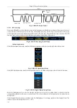
The CAN bus Tx frame structure includes the SOF, arbitration field, control field, data field, CRC field, ACK,
EOF and INT, which can be triggered on start of frame, frame type, identifier, data, identifier and data, end of
frame, missing ACK, or bit stuffing error.
SOF
1Bit
A rbit ration Field
11B its (S tandard
ID )
Control Field
6 bit s
Data Field
2 Bytes
CR C Field
16 bits
ACK
2 bits
EOF
7 bits
INT
3 bits
Fig. 11.73 CAN Bus Frame Format
11.4.1 CAN bus setup
Press down
【
Bus
】
key in the Function Area on the front panel, and the Bus setup menu will pop up on the lower
screen. (Refer to the I2C bus) As shown in the figure, click [Bus] menu key, and the Type selection menu will pop
up on the right side of the screen. (Refer to the I2C bus) As shown in the figure, click [CAN] menu key and select
the CAN bus type, and the CAN Bus setup menu will be displayed at the bottom of the screen:
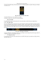
Fig. 11.74 CAN Level1 Setup Menu
Define inputs setup
Click [Define Inputs] menu key, and the CAN Input setup menu will pop up on the right side of the screen:
Fig. 11.75 CAN Define Inputs Setup Menu
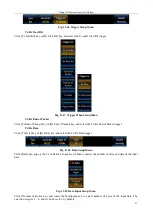
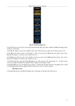
Click [CAN Input] menu key, and the CAN Input Selection Level3 Menu will pop up on the left side of the menu:
Summary of Contents for 4456 Series
Page 10: ...VIII...
Page 55: ...Chapter V Trigger System 45 Fig 5 51 RF Test Signal Example...
Page 69: ...Chapter VII Mathematical Operation 59 Fig 7 10 Advanced Math Example...
Page 71: ...Chapter VIII Display System 61 Fig 8 3 Wfm Palette Menu Fig 8 4 Normal Palette...
Page 72: ...Chapter VIII Display System 62 Fig 8 5 Inverted Palette Fig 8 6 Temperature Palette...
Page 75: ...Chapter VIII Display System 65 Fig 8 12 XY Display Example...
Page 165: ...Chapter XI Protocol Analyzer Option 155 Fig 11 242 1553 Trigger and Analysis Example...


