Parameter Description
VD300 Series Inverter User Manual
- 92 -
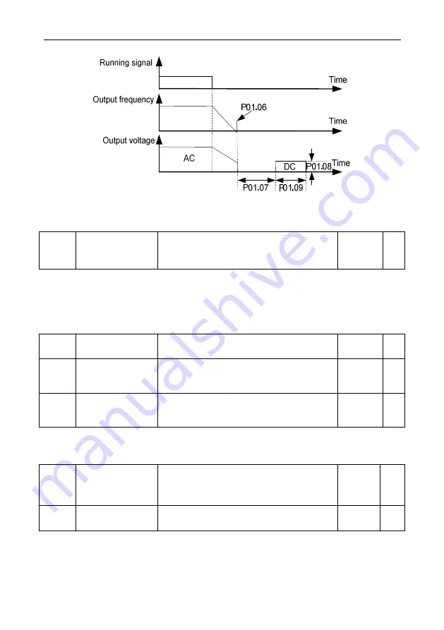
Fig 6.2-3 Schematic diagram for stop DC braking time
In the stage of DC braking, motor rotator maintains certain holding power, preventing rotator no
steady or wriggle after stop.
P01.10
Excitation Braking
Coefficient
0: Disabled
100~150: The greater the coefficient, the
greater the braking intensity
0
О
Inverter can make motor quickly reducing speed by increase motor magnetic flux. By increasing
motor magnetic flux, motor generated energy in braking can be transformed to heat.
Magnetic flux can be used in motor stop, can also be used in changing motor speed. Its feature:
braking once stopped, no need to wait magnetic flux weak then braking; furthermore, motor cooling
effect is better, during excitation braking period, motor stator current increase, rotator current not
increase, and stator cooling is faster than rotator.
P01.11
Short-circuit
Braking Current
0.0%~150% (100% relate to inverter rate
current)
0.0%
О
P01.12
Startup Short-circuit
Braking Holding
Time
0.00s~60.00s
0.00s
О
P01.13
Stop Short-circuit
Braking Holding
Time
0.00s~60.00s
0.00s
О
When the parameter value is set to a non 0, inverter output in start and stop is equivalent to get short
circuit of U, V, W motor output.
P01.12 and P01.13 separately used to set start or stop short circuit braking retention time.
P01.14
Switchover Mode
between FWD/REV
Rotation
0: Switchover with zero frequency
1: Switchover with over starting frequency
2: Switchover at stop speed reach and delay
0
◎
P01.15
FWD/REV Rotation
Dead-zone Time
0.0s~3600.0s
0.0s
О
When motor is switchover to reverse direction, can select direct over-zero frequency switchover, can
also select start frequency switchover, or after motor reduce to 0 speed then switchover through
forward/reverse dead zone time. As below diagram showed:
Содержание VD300 Series
Страница 2: ......


