VD300 Series Inverter User Manual
Parameter Description
- 151 -
6.13 P13 Protection Function Parameters Group
P13.00
Motor 1 Overload
Protection Selection
0: Disabled
1: Ordinary motor(with low speed
compensation)
2: Variable frequency motor (without low
speed compensation)
2
○
P13.01
Motor 1 Overload
Protection Coefficient
20.0%~200.0%
100.0%
○
P13.02
Motor 2 Overload
Protection Selection
0: Disabled
1: Ordinary motor(with low speed
compensation)
2: Various frequency inverter(without low
speed compensation)
2
○
P13.03
Motor 2 Overload
Protection Coefficient
20.0%~200.0%
100.0%
○
Start motor overload software protection function, via checking the inverse time limit curve feature
when inverter has motor overload protection, in order to judge if motor is in overload state.
Closing motor overload software protection function, may has the risk of overheat damage to motor, it
is highly recommended to add a thermal relay between inverter and motor to protect motor when
setting the parameter.
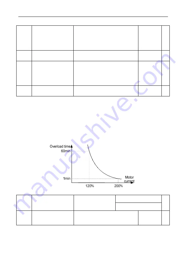
The inverse time limit curve of motor overload protection default as: 200% motor rate current, last
1min then alarming motor overload error; 120% motor rate current, keep 60min then alarming motor
overload error. Via adjusting motor overload protection coefficient to smoothening motor overload
curve, to meet the actual application of specific motor.
The bigger the overload protection coefficient is, the longer the overload time is.
Fig 6.12-1 Motor overload curve
G: 150%
P13.04
Inverter or Motor
Overload Warning
Detection level
50%~200%
P: 120%
○
P13.05
Inverter or Motor
Overload Warning
Detection Time
0.0s~3600.0s
1.0s
○
Inverter or motor overload pre-alarming detection level: before inverter or motor overload error
protection, through DO send a pre-alarm signal to control system. The pre-alarm factor is to decide
what time to pre-alarm before inverter or motor overload protection. The bigger the value is, the
smaller the pre-alarm advanced quantity is.
Содержание VD300 Series
Страница 2: ......


