Parameter Description
VD300 Series Inverter User Manual
- 98 -
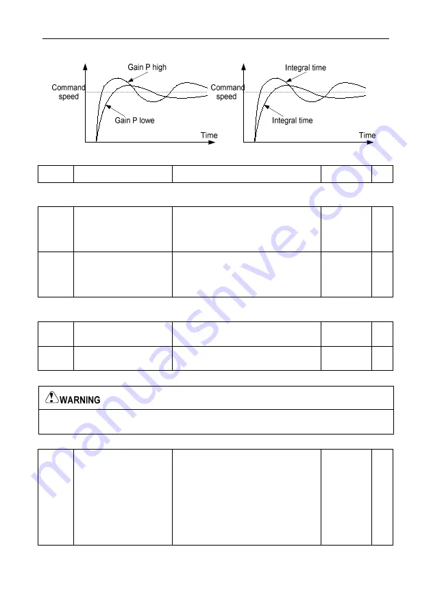
adjusted based on actual situation. As shown in the figure below:
Fig 6.4-2 Schematic Diagram for speed loop PI parameter
P03.07
Speed Loop Output Filter
0~8 (corresponding 0~2^8/10ms)
0
○
Speed loop output filter: speed loop output via first-order filter was sent to current controller, by
increasing this filter to decrease the output current ripple, but dynamic response will be slow down.
P03.08
Vector Control Slip
Compensation
Coefficient
(Motoring Condition)
50.0%~200.0%
100.0%
○
P03.09
Vector Control Slip
Compensation
Coefficient
(Generating Condition)
50.0%~200.0%
100.0%
○
Slip compensation factor is used in adjusting vector control slip frequency, to improve system speed
control precision, properly adjust the parameter, can effectively suppress speed offset.
P03.10
Current Loop Proportion
Coefficient P
0~60000
1000
○
P03.11
Current Loop Integral
Coefficient I
0~60000
1000
○
Above current loop PI adjusting parameter is only applied for vector control mode 1.
The two parameters in PI adjustments of the current loop, it directly affect the system’s dynamic
response speed and control precision, in general case, the user does not need to adjust.
P03.12
Torque Setting Mode
Selection
0: Function code P03.13
1: AI1
2: AI2
3: AI3 (extension card)
4: High speed pulse input
5: Communication setting
Notes: 100% of 1~4 corresponding
P03.13
0
○
Vector torque control, torque command can be set by function code P03.13, can also be set by
analog, HS pulse input, communication given. 100% of 1~4 full scale corresponding P03.13.
Содержание VD300 Series
Страница 2: ......


