E6582175
E-17
5
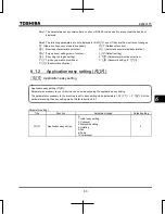
Note) When the other preset-speed command is input while adjusting frequency with the setting dial, operation
frequency will change but not the inverter display and the subject of adjustment.
Ex) If
sr2
is input when operating under
sr1
and changing frequency with the setting dial, operation
frequency will change to
sr2
but inverter display and the subject of adjustment continue to be
sr1
.
Press the center or MODE key to display
sr2
.
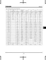
Preset-speed logic input signal example: Slide switch SW1 = SINK side
O: ON -: OFF (Speed commands other than preset-speed commands are valid when all are OFF)
Terminal
Preset-speed
1
2
3
4
5
6
7
8
9
10
11
12
13
14
15
S1-CC
-
-
-
-
-
-
-
S2-CC
-
-
-
-
-
-
-
S3-CC
-
-
-
-
-
-
-
RES-CC
-
-
-
-
-
-
-
●
Terminal functions are as follows.
Terminal S1 ............. Input terminal function selection 4A (S1)
=
10
(Preset-speed command 1: SS1)
Terminal S2 ............. Input terminal function selection 5 (S2)
=
12
(Preset-speed command 2: SS2)
Terminal S3 ............. Input terminal function selection 6 (S3)
=
14
(Preset-speed command 3: SS3)
Terminal RES
Input terminal function selection 3A (RES)
=
16
(preset-speed command 4: SS4)
●
In the default settings, SS4 is not assigned. Assign SS4 to RES with input terminal function selection.
CC
S1
S2
RES
S3
F (Forward run)
CC
RES
S2
S3
S1
Forward
Preset-speed 1 (SS1)
Preset-speed 3 (SS3)
Preset-speed 4 (SS4)
Preset-speed 2 (SS2)
Common
[ Example of a connection diagram ]
(with sink logic settings)
Содержание TOSVERT VF-S15 series
Страница 394: ......


