


FUNCTION CHARACTERISTICS
97
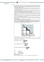
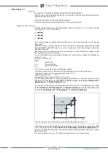
The first threshold trip (
U
<) may be inhibited by start of the second threshold (
U
<<) by setting
ON
the U< Disabling by U<< start (
U<disbyU<<
) parameter available inside the
Set \ Profile A (or B) \
Undervoltage-27 \ U<< Element \ Setpoints
menu.
User can disable both 27 protection thresholds from the keyboard. During this command, the trip
output relay (U <and / or U << thresholds) are forced to reset state, the message “27 Disabled” is
displayed and all LEDs blink until the end of the command.
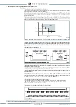
Breaker failure (BF)
Each thresholds ( U <, U <<) can be associated to BF (H) and BF (L) protection by activating the rel-
ative parameter in the matrices “Selection of function tripping for BF (H)” or “Selection of function
tripping for BF (L)” in relevant
BF
menus
[1]
:
• Set \ Profile A (or B) \ Breaker failure - BF side H
• Set \ Profile A (or B) \ Breaker failure - BF side L
VT monitoring (74VT)
Both the protection elements are blocked off whenever the VT supervision function is active, so
that no unwanted trip can arise if any fault on the VTs secondary circuits (break, fuse trip, etc)
are detect;
[2]
the Block functions enable from 74VT parameter
74VT-BK-EN
is available inside the
Set \ VT supervision -74VT.
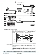
For every of the two elements the logic block is available:
Logical block (Block1)
If the
U<BLK1
and/or
U<<BLK1
enabling parameters are set to
ON
and a binary input is designed
for logical block (Block1), the protection is blocked off whenever the given input is active.
The trip timer is held in reset condition, so the operate time counting starts when the input block goes
down.
[3]
The enabling parameters are available inside the
Set \ Profile A (or B) \ Undervoltage - 27
\
U< Element
(
U<< Element) \ Setpoints
menus, while the
Block1
function must be assigned to the
selected binary input inside the
Set \ Board1(2) inputs \ Binary input IN1-1...INx-x
menus.
All parameters can be set separately for A and B setting profiles
Note 1 The common settings concerning the Breaker failure protection are adjustable inside the
Breaker Failure - BF
menu.
Note 2 The exhaustive treatment of the VT supervision function may be found in the “VT supervision - 74VT” paragraph inside
CONTROL AND MONI-
TORING
section.
Note 3 The exhaustive treatment of the logical block (Block 1) function may be found in the “Logic Block” paragraph inside
CONTROL AND MONITOR-
ING
section.
all-F27.ai
U< Element
U<< Element
MMI
Start U<<
Start U<<
Start U<
Trip U<
Trip U<<
&
U< disbyU<<
&
U< inhibition
t
U< def
t
U< inv
U<
def
t
U<< def
U<<
def
U<
inv
U< Curve
U< Enable
State
Block1
BLK1U<
&
U<BLK1
Start U<
&
Block1
BLK1U<<
&
U<<BLK1
Start U<<
&
U
74VT
&
U
74VT
AND
U
12
,
U
23
,
U
31
U
U
L1
,
U
L2
,
U
L3
OR
Common configuration
Utype27
Disable 27-37-81 functions by operator
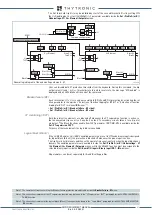
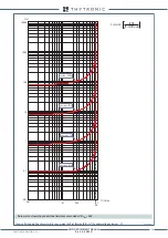
Logic27
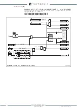
General logic diagram of the undervoltage elements - 27
XMR-D EQUIPMENT MANUAL
Ed. 2.9 - 02/2021


